
![]()
Contents
Fuel Rail + Regulator Kit (Return Style Kit)
- Remove Fuel Pump
- Modify Fuel Pump Basket for Return Line and Install Regulator Plug
- Install Fuel Rail, Injectors and Regulator
- Install Fuel Lines
- Reinstall Air Box
- Flash ECU
- Reinstall All Remaining Parts
Fuel Rail + Pulsation Damper Kit Installation (Returnless Style Kit)
Application Notes
Supported models: 2016+ Yamaha YXZ 1000 (all trims)
The vehicle shown in this document is a modified 2021 Yamaha YXZ 1000R.
Your vehicle could have parts that may or may not be present in the pictures. The pictures are meant to be a reference only.
If you have any questions regarding your installation, contact us at support@injectordynamics.com.
Item List
| Yamaha YXZ Fuel System Kit Components | |||||
|---|---|---|---|---|---|
| Item # | Description | Qty | Fuel Rail + Regulator Kit (Return Style Kit) | Fuel Rail + Pulsation Damper Kit (Returnless Style Kit) | Fuel Rail Upgrade Kit |
| 1 | Yamaha YXZ Fuel Rail | 1 | |||
| 2 | 3 bar Pressure Regulator / Pulsation Damper ASY | 1 | |||
| 3 | Stock Fuel Pressure Regulator Plug | 1 | |||
| 4 | M5 X 25mm Socket Head Flange Bolt | 2 | |||
| 5 | 06 ORB to 06AN Male | 1 | |||
| 6 | 06 ORB to 04AN Male | 1 | |||
| 7 | 06 ORB to 06 ORB Coupler | 1 | |||
| 8 | 06 ORB Plug | 1 | |||
| 9 | 90° 06AN Male to 5/16 EFI (Press On) | 1 | |||
| 10 | 06 Feed Hose (44.5″) w/ Straight and 90° Fittings | 1 | |||
| 11 | 04 Return Hose (55″) w/ Straight and 45° Fittings | 1 | |||
| 12 | 04 AN 90° Bulkhead | 1 | |||
| 13 | 04 AN Bulkhead Nut | 1 | |||
| 14 | 04 AN Stat-O-Seal | 1 | |||
| 15 | 4mm Wye Barb Connector | 1 | |||
| 16 | 4mm Black Silicone Hose (4″) | 1 | |||
| 17 | 4mm Black Silicone Hose (12″) | 1 | |||
| 18 | 3″ Miniature Cable Ties | 5 | |||
| 19 | 11″ Cable Tie | 5 | |||
Fuel Rail + Regulator Kit (Return Style Kit)
1. Remove Fuel Pump
- Remove the passenger seat cushion and unfasten (4) bolts shown with red arrows in figure 1 to remove the seat back.
- Remove center console covers shown in figure 2.
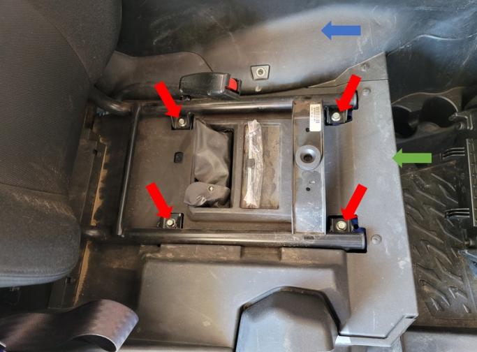
Figure 1: Seat hardware and panel reference.
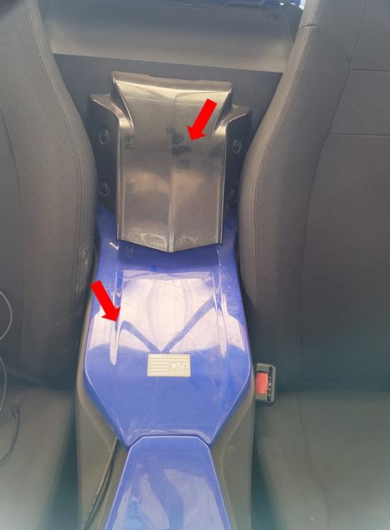
Figure 2: Center Console panel reference.
- Remove the passenger side tunnel panel pointed out by the blue arrow in figure 1.
- Remove the gas cap and lower side panel shown in figure 3. Reinstall gas cap.
- Remove the seat bottom cover panel pointed out by the green arrow in figure 1.
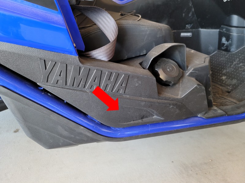
Figure 3: Lower side panel reference.
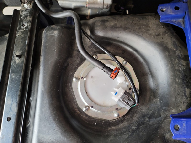
Figure 4: Pump Basket reference.
- Disconnect the power connector and crank the engine to bleed fuel pressure. Disconnect the battery.
- Disconnect the fuel line from the pump basket. There will still be some fuel left in the fuel line.
- Mark the location that needs to be drilled for the return line bulkhead fitting. (Refer figure 5)
- Remove the six crown nuts to remove the retaining plate and lift the fuel pump assembly out of the tank.(drain as much fuel back into the tank as possible)
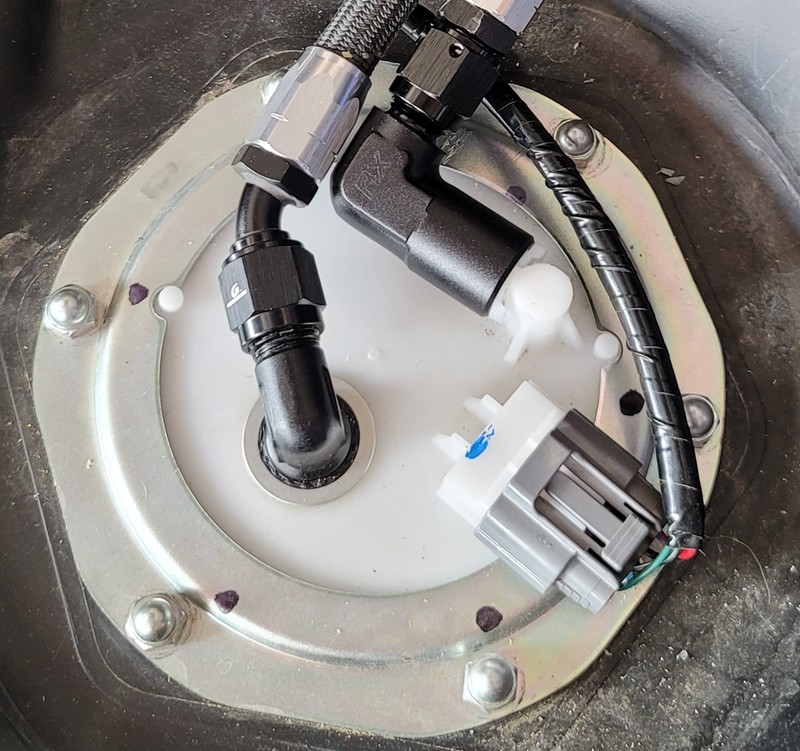
Figure 5: Return Line Location.
2. Modify Fuel Pump Basket for Return Line and Install Regulator Plug
- Drill a 7/16” hole where the mark was made in the previous step. A Unibit step drill is recommended but it is also possible to start with a smaller drill bit and step up to a 7/16” bit.
- Install the 90° bulkhead fitting using the stat-o-seal on top of the pump basket. Refer to Figure 5.
- Install the EFI adapter onto the outlet of the fuel pump by removing the plastic clip from the adapter and installing it onto the outlet of the pump basket first. After the plastic clip is seated correctly, press on the metal portion of the adapter. Pull on the adapter to ensure proper installation. Use figure 6 as a reference.
- To gain access to the pressure regulator, lift the 5 blue plastic clips shown in figure 7.
- Remove the regulator and transfer the plastic ring over to the supplied plug, under the larger O-ring. Install the plug into the housing, refer to figure 8.
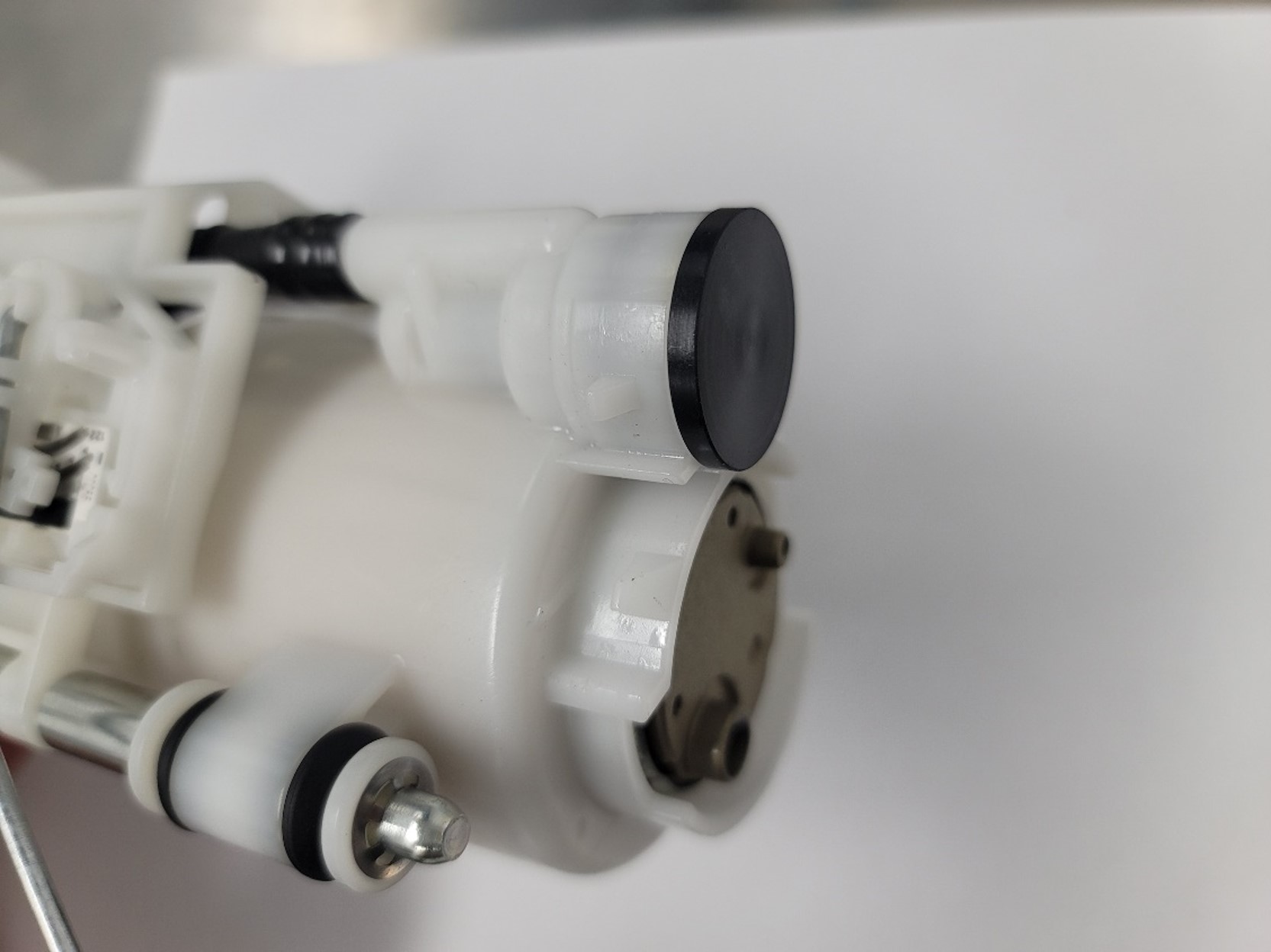
Figure 8: Installed Regulator Plug.
- Reassemble pump assembly
- Reinstall fuel pump assembly into the fuel tank. Use figure 5 as a reference for all connections.
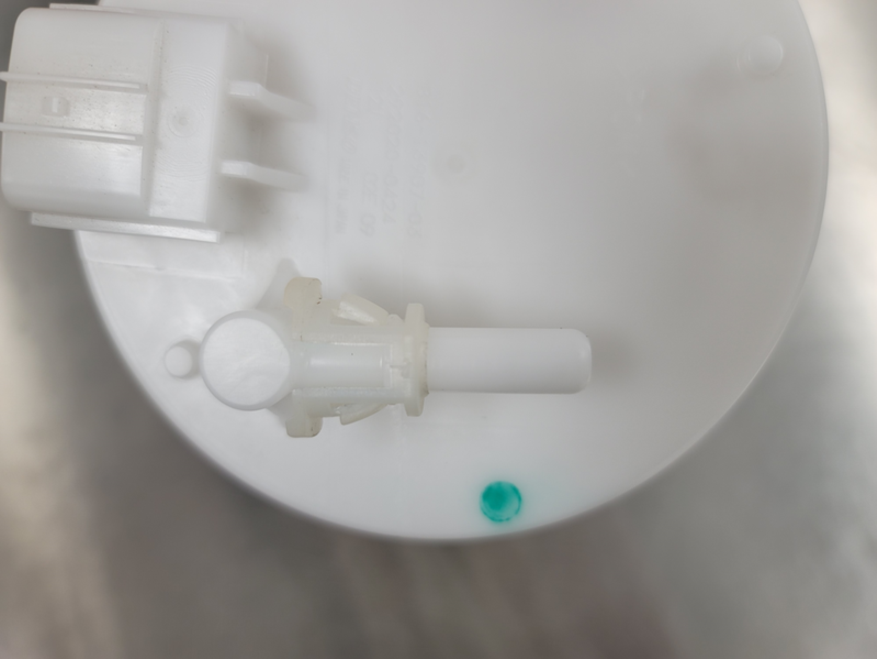
Figure 6: EFI Fitting Install Reference.
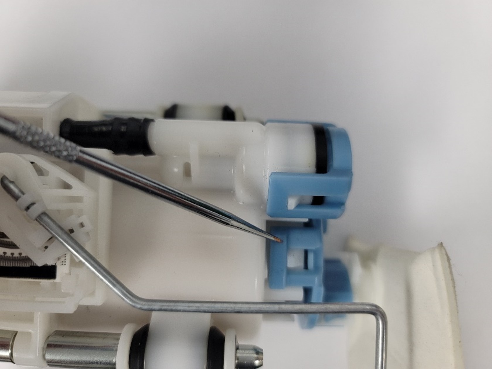
Figure 7: Clip Reference.
3. Install Fuel Rail, Injectors and Regulator
- Remove the engine cover and all 4 side covers identified in figure 9.
- Remove the driver seat using the same steps as the passenger seat.
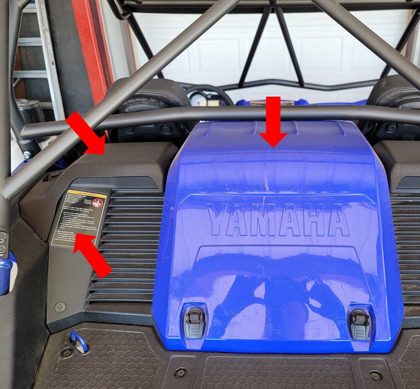
Figure 9: Rear Panel Reference
- Remove firewall panel located behind the seats.
- Remove air box. Make sure to disconnect the electrical connector and all hoses.
- Disconnect injector electrical connectors.
- Disconnect fuel line from rail.
- Remove (2) M5 bolts to uninstall the fuel rail and injectors. Make sure to set aside the lower factory seals because they will be reused.
- Install the -06 ORB fittings. Use figure 10 as a reference.
- Install the -06 ORB to -06 AN fitting on the inlet of the rail towards the front of the vehicle.
- Install the -06 ORB swivel fitting (non adjustable side) on the outlet of the rail towards the rear of the vehicle.
- Install -06 ORB to -04 AN fitting into the bottom of the regulator housing.
- Thread on the regulator housing to the swivel fitting until the threads bottom out, then back out one turn. Do not tighten the lock nut.
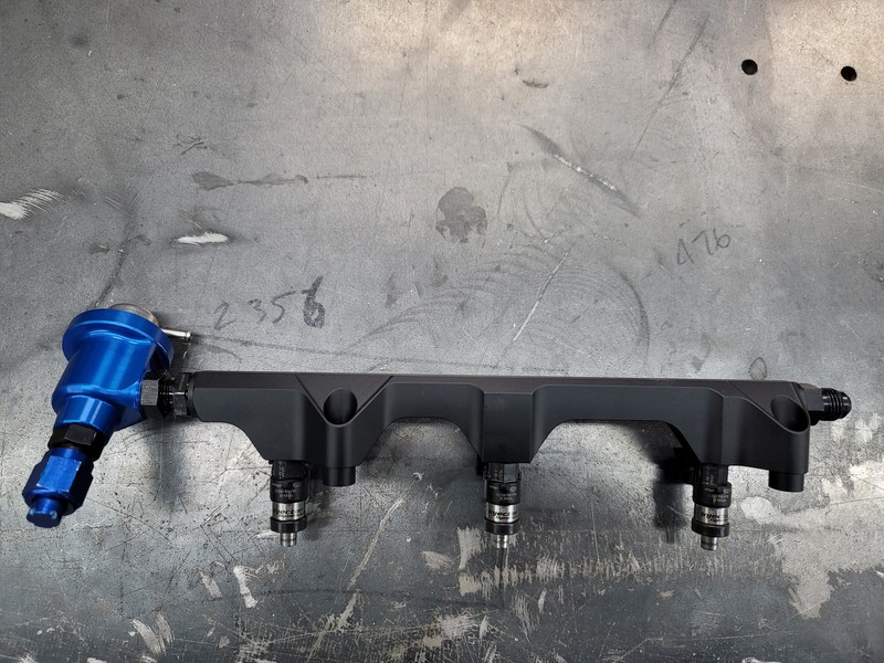
Figure 10: Rail Assembly Reference
- Install ID injectors into the fuel rail (Apply some grease on all O-rings)
- Install fuel rail and injectors onto throttle body ensuring to properly seat the bottom of the injector on the factory cushions (Take care to not over tighten bolts).
- Tighten the lock nut to the regulator housing. Use figure 11 as a reference to the regulator housing orientation.
- Connect injector connectors using the supplied electrical adapters.
- Push on the supplied long 4mm vacuum hose onto the pressure regulator barb.
- Tie into the factory vacuum line:
- Remove the hose from the rear pressure sensor show in figure 12 and push on the supplied short 4mm hose trim.
- Use the supplied 4mm Y connector to connect the 3 vacuum hoses. Use figure 12 for reference. Trim any excess length.
- Zip tie all hose ends with supplied 3” cable ties.
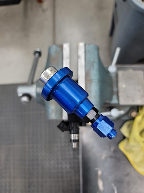
Figure 11: Regulator orientation reference.
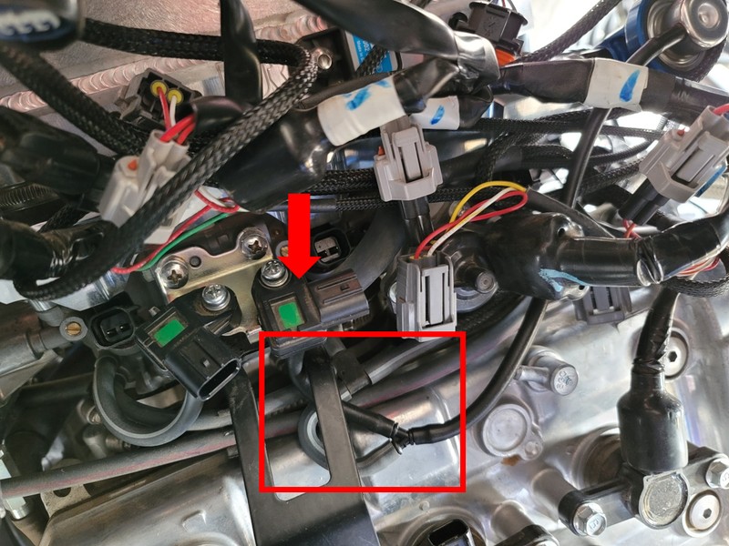
Figure 12: Vacuum plumbing reference
4. Install Fuel Lines
- Remove factory fuel line from vehicle.
- Starting with the -06 feed line (larger), connect the 90° fitting to the fuel rail towards the front of the car. Use figure 13 as a reference for the hose routing. Connect the straight fitting to the EFI adapter.
- Connect the straight fitting of the -4 return line to the outlet of the fuel pressure regulator.
- Route the return line alongside the feed line towards the fuel tank.
- Connect the 45° fitting to the bulkhead fitting. Use figures 13 and 14 as references.
- Zip-tie the fuel hoses together and along the center console rail as shown in figure 11.
- Reconnect the battery and prime the fuel system to check for leaks. Do not start the vehicle.
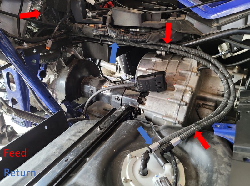
Figure 13: Fuel Line Reference.
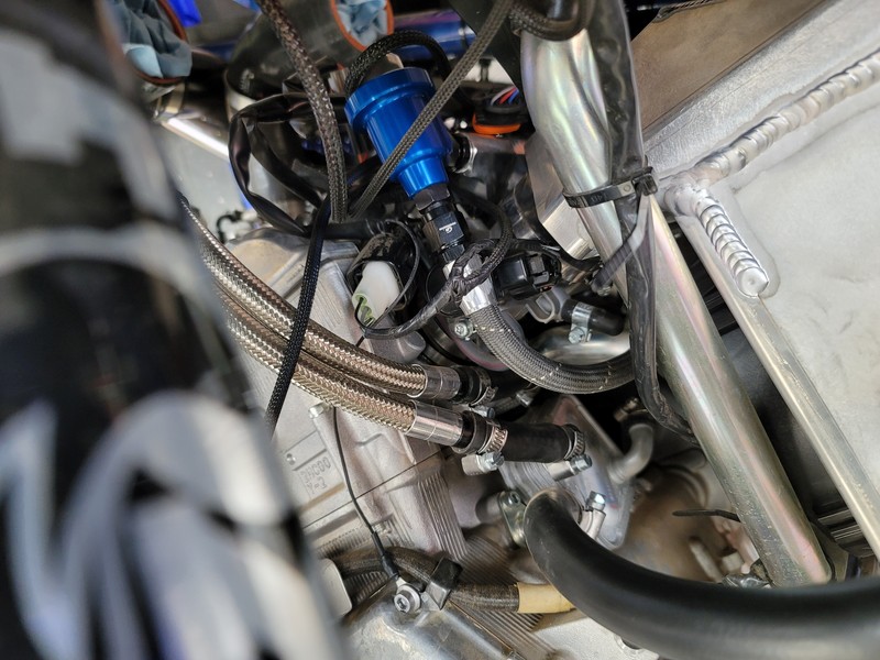
Figure 14: Return line reference. (-06 Line Shown in image).
5. Reinstall Air Box
- Reinstall the airbox in the reverse order that it was removed.
6. Flash ECU
- Generate ECU data by using the following online generator and follow the directions to make the changes in the calibration.
- Once the ECU flash is complete, start the vehicle ensuring that there are no leaks in the fuel system. (Always have a fire extinguisher close by).
Dynojet PV3 Yamaha Data Generator
7. Reinstall All Remaining Parts
- Once you have ensured there are no leaks, reinstall all body panels and seats in the reverse order of removal.
Fuel Rail + Pulsation Damper Kit Installation (Returnless Style Kit)
1. Access the Fuel Pump
- Remove the passenger seat cushion and unfasten (4) bolts shown with red arrows in figure 1 to remove the seat back.
- Remove center console covers shown in figure 2.
Figure 1: Seat hardware and panel reference.
Figure 2: Center Console panel reference.
- Remove the passenger side tunnel panel pointed out by the blue arrow in figure 1.
- Remove the gas cap and lower side panel shown in figure 3. Reinstall gas cap.
- Remove the seat bottom cover panel pointed out by the green arrow in figure 1.
Figure 3: Lower side panel reference.
Figure 4: Pump Basket reference.
- Disconnect the power connector and crank the engine to bleed fuel pressure. Disconnect the battery.
- Disconnect the fuel line from the pump basket. There will still be some fuel left in the fuel line.
2. Install Fuel Rail, Injectors, and Pulsation Damper
- Remove the engine cover and all 4 side covers identified in figure 5.
- Remove the driver seat using the same steps as the passenger seat.
- Remove firewall panel located behind the seats.
- Remove air box. Make sure to disconnect the electrical connector and all hoses.
- Disconnect injector electrical connectors.
- Disconnect fuel line from rail.
- Remove (2) M5 bolts to uninstall the fuel rail and injectors. Make sure to set aside the lower factory seals because they will be reused.
Figure 5: Rear Panel Reference
Figure 6: Pulsation Damper orientation reference.
Figure 7: Rail Assembly Reference
- Install the -06 ORB fittings. Use figure 7 as a reference.
- Install the -06 ORB to -06 AN fitting on the inlet of the rail towards the front of the vehicle.
- Install the -06 ORB swivel fitting (non adjustable side) on the outlet of the rail towards the rear of the vehicle.
- Install the -6 ORB plug into the bottom of the pulsation damper housing.
- Thread on the pulsation damper housing to the swivel fitting until the threads bottom out, then back out one turn. Do not tighten the lock nut.
- Install ID injectors into the fuel rail (Apply some grease on all O-rings)
- Install fuel rail and injectors onto throttle body ensuring to properly seat the bottom of the injector on the factory cushions (Take care to not over tighten bolts).
- Tighten the lock nut to the pulsation damper housing. Use figure 6 as a reference to the damper housing orientation.
- Connect injector connectors using the supplied electrical adapters.
3. Install Fuel Lines
- Remove factory fuel line from vehicle.
- Install the EFI adapter onto the outlet of the fuel pump by removing the plastic clip from the adapter and installing it onto the outlet of the pump basket. After the plastic clip is seated correctly, press on the metal portion of the adapter. Pull on the adapter to ensure proper installation. Use figure 8 as a reference.
- Connect the 90° fitting of the supplied -6 hose to the fuel rail towards the front of the car. Use figure 9 as a reference for the hose routing. Connect the straight connector to the EFI adapter.
- Zip-tie the fuel hose along the center console rail as shown in figure 9.
- Reconnect the battery and prime the fuel system to check for leaks. Do not start the vehicle.
Figure 8: EFI Fitting Install Reference.
Figure 9: Fuel line reference. Return line is not used in
this kit.
4. Reinstall Air Box
- Reinstall the airbox in the reverse order that it was removed.
5. Flash ECU
- Generate ECU data by using the following online generator and follow the directions to make the changes in the calibration.
- Once the ECU flash is complete, start the vehicle ensuring that there are no leaks in the fuel system.(Always have a fire extinguisher close by).
Dynojet PV3 Yamaha Data Generator
6. Reinstall All Remaining Parts
- Once you have ensured there are no leaks, reinstall all body panels and seats in the reverse order of removal.
Fuel Rail Upgrade Kit Installation
1. Access the Fuel Pump
- Remove the passenger seat cushion and unfasten (4) bolts shown with red arrows in figure 1 to remove the seat back.
- Remove center console covers shown in figure 2.
Figure 1: Seat hardware and panel reference.
Figure 2: Center Console panel reference.
- Remove the passenger side tunnel panel pointed out by the blue arrow in figure 1.
- Remove the gas cap and lower side panel shown in figure 3. Reinstall gas cap.
- Remove the seat bottom cover panel pointed out by the green arrow in figure 1.
Figure 3: Lower side panel reference.
Figure 4: Pump Basket reference.
- Disconnect the power connector and crank the engine to bleed fuel pressure. Disconnect the battery.
- Disconnect the fuel line from the pump basket. There will still be some fuel left in the fuel line.
2. Install Fuel Rail, Injectors and Pulsation Damper.
- Remove the engine cover and all 4 side covers identified in figure 5.
- Remove the driver seat using the same steps as the passenger seat.
- Remove firewall panel located behind the seats.
- Remove air box. Make sure to disconnect the electrical connector and all hoses.
- Disconnect injector electrical connectors.
- Disconnect fuel line from rail.
- Remove (2) M5 bolts to uninstall the fuel rail and injectors. Make sure to set aside the lower factory seals because they will be reused.
Figure 5: Rear Panel Reference
Figure 6: Pulsation Damper orientation reference.
Figure 7: Rail Assembly Reference
- Install the -06 ORB fittings. Use figure 7 as a reference.
- Install the -06 ORB to -06 AN fitting on the inlet of the rail towards the front of the vehicle.
- Install the -06 ORB swivel fitting (non adjustable side) on the outlet of the rail towards the rear of the vehicle.
- Install the -6 ORB plug into the bottom of the damper housing.
- Thread on the damper housing to the swivel fitting until the threads bottom out, then back out one turn. Do not tighten the lock nut.
- Install OE injectors into the fuel rail (Apply some grease on all O-rings)
- Install fuel rail and injectors onto throttle body ensuring to properly seat the bottom of the injector on the factory cushions (Take care to not over tighten bolts).
- Tighten the lock nut to the damper housing. Use figure 6 as a reference to the damper housing orientation.
- Connect injector connectors using the supplied electrical adapters.
3. Install Fuel Lines
- Remove factory fuel line from vehicle.
- Install the EFI adapter onto the outlet of the fuel pump by removing the plastic clip from the adapter
and installing it onto the outlet of the pump basket. After the plastic clip is seated correctly, press on the metal portion of the adapter. Pull on the adapter to ensure proper installation. Use figure 8 as a reference. - Connect the 90° fitting of the supplied -6 hose to the fuel rail towards the front of the car. Use figure 9 as a reference for the hose routing. Connect the straight connector to the EFI adapter.
- Zip-tie the fuel hose along the center console rail as shown in figure 9.
- Reconnect the battery and prime the fuel system to check for leaks. Do not start the vehicle.

Figure 8: EFI Fitting Install Reference.
Figure 9: Fuel line reference. Return line is not used in
this kit.
4. Reinstall Air Box
- Reinstall the airbox in the reverse order that it was removed.
5. Reinstall All Remaining Parts
- Once you have ensured there are no leaks, reinstall all body panels and seats in the reverse order of removal.
Sunny Wadhwa
Updated on Feb 20, 2024