
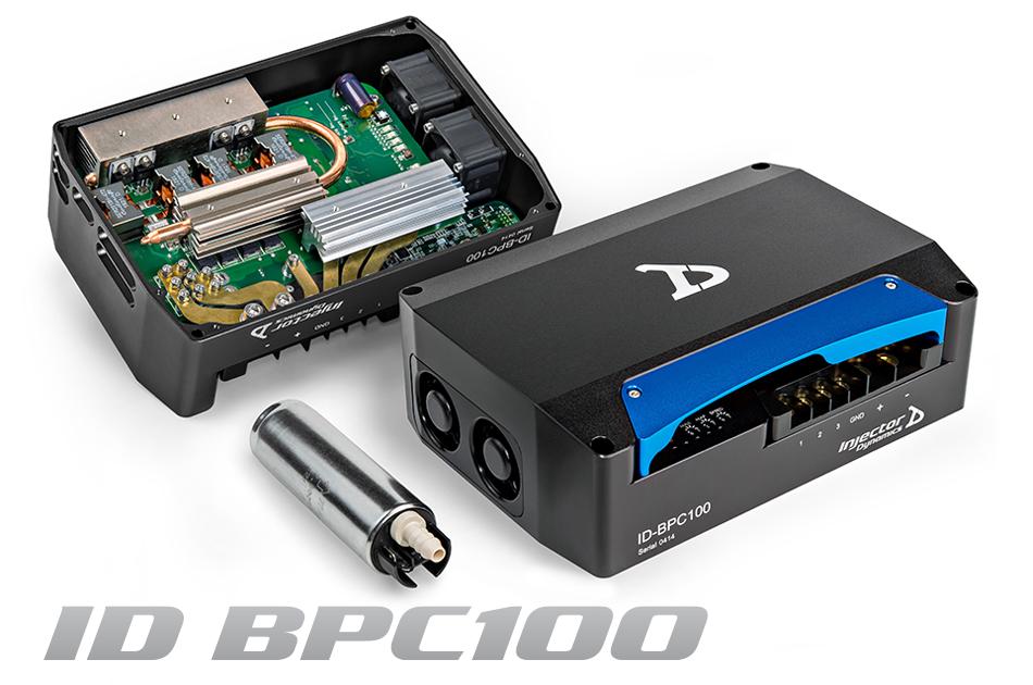
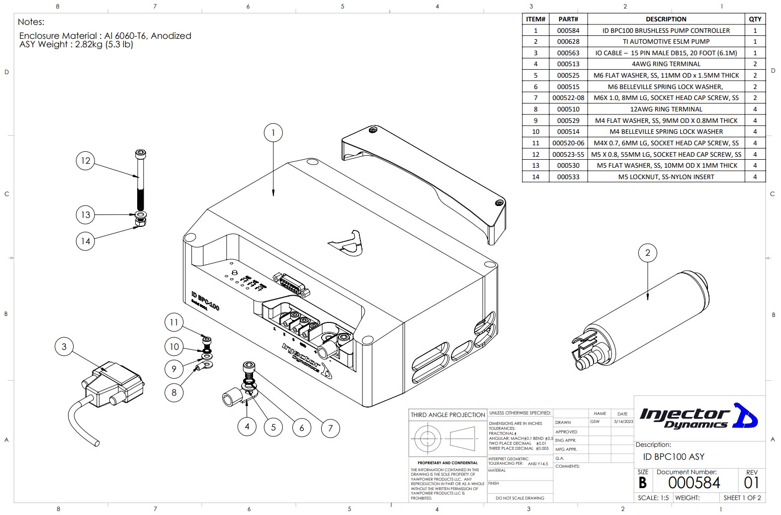
Item List
| Description | Qty |
|---|---|
| ID BPC 100 Controller | 1 |
| TI Automotive E5LM Screw Pump | 1 |
| Pump Filter Sock | 1 |
| Pump Connector | 1 |
| IO Cable – 20 foot (6.1m) 15 pin male DB15 | 1 |
| Mounting Hardware | |
| M5x55 Socket head cap screw | 4 |
| M5 Nyloc nuts | 4 |
| M5 Flat washers | 4 |
| Electrical Hardware | |
| 4 AWG Ring terminal | 2 |
| M6x8 Socket head cap screw | 2 |
| M6 Lock washer | 2 |
| M6 Flat washer | 2 |
| 12 AWG Ring terminals | 4 |
| M4x6 Socket head caps screw | 4 |
| M4 Lock washers | 4 |
| M4 Flat washers | 4 |
Installation
Mounting
- Do not mount this unit in the engine bay or anywhere exposed to water, debris or extreme heat.
- Do not use the mounting fastener holes as drill guides as this may force metal debris into the controller causing failure and/or fire.
- Any mounting orientation is acceptable as long as there is 1 inch (25mm) of clearance on both sides of the controller (the fan side and the opposing side). Mounting with less than 1” of clearance may result in overheating.
Wiring
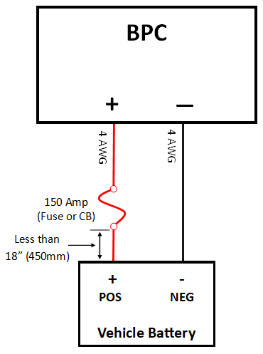
Main Power and Ground Wire Requirements
- Use high quality, pure copper 4 AWG wire with a temperature rating of at least 90° C (194° F).
- Do not use copper-clad aluminum wire, it is considerably less conductive than pure copper wire and can result in significant voltage drop. Tin plated copper wire is acceptable.
- The included power and ground terminal lugs must be securely terminated using a heavy-duty lug crimping tool.
- Use the supplied fasteners and terminal lugs to ensure sufficient fastener engagement and electrical contact.
Main Power
Main Ground
|
Figure 1: Main Power and Ground Connections. |
On/Off
- The BPC uses two wires to turn on and will do so when the ON/OFF wire has at least 7 volts and the ON/OFF Ground wire is grounded. Ensure the voltage source used for the ON/OFF wire has voltage during cranking, otherwise the BPC will turn off during cranking.
- Using an ignition (or ECU) switched power or ground will ensure the BPC turns off while the vehicle is not in use. Both high and low side switching options are shown.
IO Cable Wiring
| Signal | Wire Color | IO Cable Pin | Description |
|---|---|---|---|
| ON/OFF | Red | 1 | Ignition switched, battery +
hot during cranking, 7 vdc (min), Turns on Controller |
| ON/OFF Ground | Black | 9 | Ground for turning on controller |
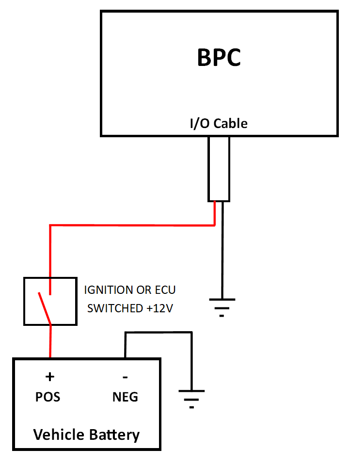
Figure 2 : ON/OFF High side switching. |
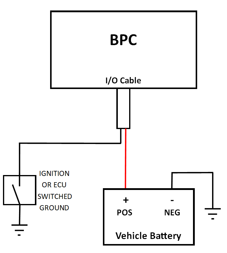
Figure 3 : ON/OFF Low side switching. |
Pump Wiring
- Use high quality, pure copper 12 AWG wire (tin plated copper is acceptable).
- Any butt connectors in use must be copper conductor (tin plated copper is acceptable).
- Any connectors, terminals or wiring in use must be rated for 25 amps continuous.
- An 18 AWG (minimum) pump ground is REQUIRED to be connected to a chassis ground. It is typically easiest to loop from the pump ground connection (labeled GND) to the BPC main ground connection (labeled —). Alternatively, a local chassis ground using solid, bare sheet metal and a ring terminal is acceptable.
- Use the supplied fasteners and terminal lugs to ensure sufficient fastener engagement and electrical contact.
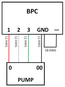
Figure 4: Pump output wiring.
Mode Specific Wiring
Each mode of operation may require specific wiring. Please see the Control Mode section for specific wiring instructions.
Pump Installation
- This pump is designed only for submerged (in-tank) applications, do not use externally.
- Fuel lubrication is required because this pump achieves higher flowrates at greater pressures than the original design intent. Lubricating the fuel decreases current draw and increases service life by 20x at elevated flowrates and pressures.
- We recommend Klotz Uplon (KL-107) at the following ratios.
| Ethyl/Methyl Alcohols | 170:1 (0.75 oz/Gal) |
| Gasoline | 256:1 (0.50 oz/Gal) |
Plumbing
- Because this pump has flowrates and pressure capabilities similar to a mechanical fuel pump, proper diameter plumbing is critical. Fuel systems with undersized supply lines, reduced diameter adapters or small radius bends will have a significant pressure drop between the fuel pump and fuel pressure regulator. This will, at minimum, cause additional fuel heating, current draw and pump wear.
- Use a minimum of -8AN (1/2” diameter tubing) for both supply and return.
- Use a fuel pressure regulator sized appropriately for -8AN, capable of bypassing 1000+ lph without excessive fuel pressure increase.
- Use a fuel filter designed to flow 1200lph with minimal pressure drop. We recommend using the ID F1250 inline fuel filter.
- Limit the number of undersized fittings, 90 degree and small radius bends.
Control Modes
Overview
The BPC has three modes of operation; PWM, MAP and Constant flow.
- PWM mode allows complete control of the fuel pump flowrate.
- The flowrate is commanded by a user-defined input signal, from an ECU or a logger/dash with a pulse width modulated (PWM) auxiliary output.
- This mode does not use the onboard dials.
- MAP mode controls the fuel pump flowrate based on intake manifold pressure.
- The manifold pressure is measured via a dedicated MAP sensor referenced to the intake manifold. Users define the maximum fuel pump flowrate and the manifold pressure when the maximum flowrate is reached by adjusting two dials onboard the controller.
- This mode allows pump flowrate control without the use of an ECU/logger/dash but requires the installation of a dedicated MAP sensor.
- Constant flow mode keeps the fuel pump flowrate constant.
- The fuel pump flowrate is adjusted using a dial onboard the controller.
PWM Mode
Operation
- PWM mode controls the fuel pump flowrate based on a user-controlled PWM input signal.
- This allows the user complete control by setting up the ECU (or logger/dash) output as a function of other parameters (i.e. engine fuel flow, engine speed, manifold pressure, etc.).
- The pump flowrate is scaled linearly with PWM input duty cycle; the minimum flow rate is achieved at 10% duty cycle and maximum flowrate at 90% duty cycle.
| Input PWM (%) | Pump Flow Rate (lph) |
| 10 | 300 |
| 90 | 1100 |
Setup
- Fuel pump flowrate is controlled via PWM input signal using the PWM + and PWM – inputs.
- PWM uses a fixed frequency square waveform with a varying duty cycle. The PWM frequency must be between 80 and 1000 Hertz with at least +5 volts (between PWM + and PWM –).
- If the ECU (or logger/dash) has minimum and maximum duty cycle limits, set them to 10% and 90%, respectively. Setting these limits ensures the controller will never unexpectedly shut down or change operation modes from an improper PWM input.
- If the controller receives a 100% input duty cycle, the operation mode will change to constant flow and will revert back to PWM mode when the duty cycle is less than 100%.
- The controller calculates input duty cycle via negative polarity, which is based on the time the PWM signal is low. This means an input duty cycle of 10% would be high 90% of the time and low 10%. If the controller is wired to be high side switching, the PWM duty cycle may be inverted.(depending on the ECU)
PWM Mode High Side Switching Wiring
| Signal | Wire Color | IO Cable Pin | Description |
|---|---|---|---|
| PWM + | Red / White | 2 | PWM pulsed positive input,
5 vdc (min), Used to control pump speed. |
| PWM – | Black / White | 10 | Local chassis ground |
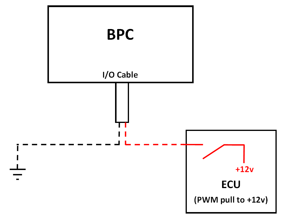
Figure 5: PWM Mode high side switching wiring.
PWM Mode Low Side Switching Wiring
| Signal | Wire Color | IO Cable Pin | Description |
|---|---|---|---|
| PWM + | Red / White | 2 | Connected to Battery,
7-17 VDC, |
| PWM – | Black / White | 10 | PWM pulsed ground,
Used to control pump speed |
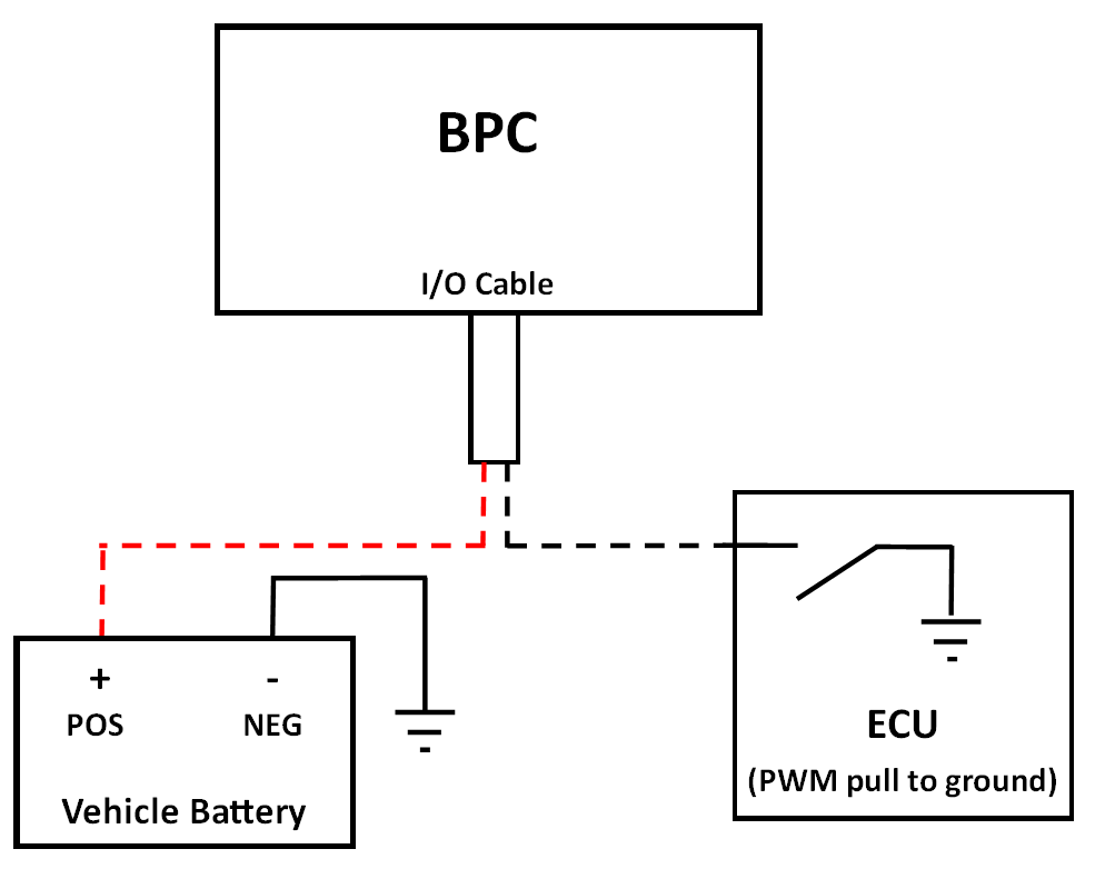
Figure 6: PWM Mode low side switching wiring.
MAP Mode
Operation
MAP mode controls the fuel pump flowrate based on intake manifold absolute pressure (MAP). Because engine fuel flow requirements typically increase with increasing MAP pressure, the pump flowrate will also increase.
Setup
- This mode REQUIRES the installation and use of a 7 bar (or 100psi) absolute, ratiometric (0.5-4.5vdc output) MAP sensor with a current draw less than 20mA. DO NOT use an existing ECU/Engine MAP sensor.
- There is onboard +5vdc power (orange wire, pin 15) and ground (green wire, pin 14) for the dedicated MAP sensor.
- The MAP sensor should be installed in or use a line from the engine side of the throttle body from a common plenum, not a single runner.
Adjustment dials
-
- The MAX, MAP and SPEED dials only rotate 210°, from the minimum indicator (~8 o’clock), clockwise to the max indicator (~4 o’clock). Do not force them past these positions.
- Use the provided jewelers screw driver to avoid damage.
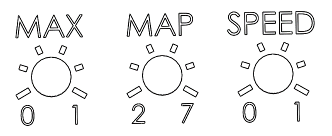
Figure 7: MAP Mode Adjustment Dials.
- MAX DIAL – Sets the max pump flowrate. For a max flow of approximately 500 lph turn full counterclockwise, max flow of 1100 lph is full clockwise.
- MAP DIAL – Sets the MAP pressure at which maximum flowrate is reached. For max flow at 2 bar turn full counterclockwise, max flow at 7 bar is full clockwise.
- SPEED DIAL – The SPEED dial is not used in MAP mode but should be set to max(full clockwise) as a safety precaution in the case of a MAP sensor failure or disconnection. If the MAP sensor fails low (zero volt signal) or is unplugged, the controller will revert to constant flow mode.
- The pump minimum flowrate is fixed at 300 lph from 0 kPa through 50 kPa. After 50 kPa the pump flowrate will increase linearly based on the MAX and MAP dial settings.
Wiring
For this operation mode, the PWM + and PWM – wires may be wired with (electrically connected to) the ON/OFF and ON/OFF Ground wires, respectively. By wiring these together, the controller turns on and into MAP Mode when the PWM + and ON/OFF wires are both at +12V, the PWM – and ON/OFF Ground wires are grounded and the MAP Signal wire has at least +0.25 volts.
| Signal | Wire Color | IO Cable Pin | Description |
|---|---|---|---|
| PWM + | Red / White | 2 | Ignition switched, battery +
hot during cranking, 5 vdc (min) |
| PWM – | Black / White | 10 | Local chassis ground |
| MAP Ground | Green | 14 | Ground output to MAP sensor |
| MAP Power | Orange | 15 | +5 vdc output to MAP sensor,
20mA max |
| MAP Signal | Purple | 8 | MAP sensor signal input,
0.5 to 4.5 vdc |
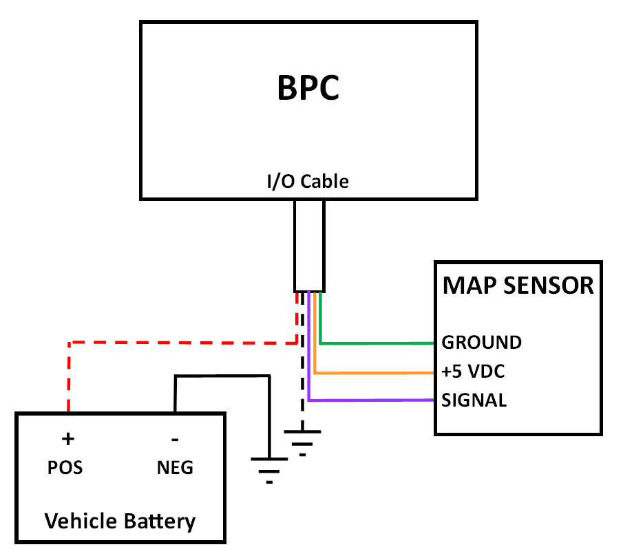
Figure 8: MAP Mode specific wiring.
Constant Flow Mode
Operation
Constant speed mode runs the pump at a fixed flowrate. This can be useful for initial fuel system priming, leak checking or troubleshooting.
Setup
Adjustment dials
-
- The MAX, MAP and SPEED dials only rotate 210°, from minimum indicator (~8 o’clock), clockwise to max indicator (~4 o’clock). Do not force them past these positions.
- Use the provided jewelers screw driver to avoid damaging them.
- SPEED DIAL – The flowrate is adjusted by the SPEED dial. Set to full clockwise (1 on dial) for maximum flowrate and full counterclockwise (0 on dial) for minimum flowrate.
Figure 9: Constant Flow Mode Adjustment Dial.
Wiring
For this operation mode, the PWM + and PWM – wires may be wired with (electrically connected to) the ON/OFF and ON/OFF Ground wires, respectively. By wiring these together, the controller turns on and into Constant Flow Mode when the ignition is on.
Alternatively, the PWM+ and PWM- wires may be wired using a fuel pump enable wire (which typically switches to ground). When the PWM + and ON/OFF wires are both at +12V and the PWM – and ON/OFF Ground wires are grounded, the controller will be in Constant Flow Mode. This is a low current input and does not require a relay.
| Signal | Wire Color | IO Cable Pin | Description |
|---|---|---|---|
| PWM + | Red / White | 2 | Ignition switched, battery +
hot during cranking, 5 vdc (min), Starts Pump |
| PWM – | Black / White | 10 | Local chassis ground for turning on controller |
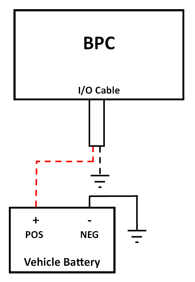
Figure 10: Constant Speed Mode specific wiring.
Outputs
Flowrate
- The pump flowrate can be monitored or logged using the Flowrate Signal and Flowrate Ground wires when CAN logging is not available.
- When the Flowrate Ground (brown) is grounded and the Flowrate Signal (pink) is connected to an ECU digital input with an internal pull-up resistor, the frequency is directly proportional to pump flowrate (i.e.300Hz=300lph).
| Signal | Wire Color | IO Cable Pin | Description |
|---|---|---|---|
| Flowrate Ground | Brown | 11 | Ground for Flowrate circuit,
chassis ground |
| Flowrate Signal | Pink | 4 | Digital signal output to logger for flowrate datalogging |
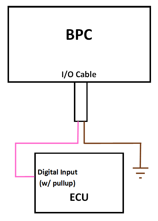
Figure 11: Flowrate output wiring.
CAN
Pump and controller information is broadcast via CAN bus.
CAN Parameters
- DBC File Template – Please visit the downloads section at the end
- Baud Rate : 1 Mbps
- CAN wiring requires 120 ohm resistors on both ends of the CAN line. Note: These are not additional resistors, only two are required per CAN bus. If using existing CAN wiring, these resistors are likely already in place.
| CAN Message 1, 0x300 (extended) | |||||
|---|---|---|---|---|---|
| Byte | Name | Factor | Offset | Units | Description |
| 0 | Input Voltage | 0.088 | 0.8 | Volts | Main power input voltage |
| 1 | Input Current | 0.5937 | -18.227 | Amps | Main power input current |
| 2 | Pump Current | 0.2144 | 0 | Amps | Pump output current |
| 3 | Flow Rate | 4.72441 | 200 | Liters/Hour | Pump flowrate |
| 4 | Board Temp | 0.588235 | 0 | Celsius | Main board temperature |
| 5 | Not Used | – | – | – | – |
| 6 | Pump Output DC | 0.394 | 0 | % | Pump output PWM duty cycle |
| 7 | Status | 1 | 0 | – | Pump/Controller Status (See notes below) |
| CAN Message 2, 0x301 (extended) | |||||
|---|---|---|---|---|---|
| Byte | Name | Factor | Offset | Units | Description |
| 0 | Input PWM DC | 0.394 | 0 | % | Input PWM duty cycle |
| 1 | MAP voltage | 0.02 | 0 | Volts | Voltage from MAP sensor signal |
| 2 | Phase | 1 | 0 | Steps | Electrical phase advance for pump |
| 3 | Pump Current AVG | 0.2144 | 0 | Amps | Average pump output current |
| 4 | Flow Rate AVG | 4.72441 | 200 | Liters/Hour | Average pump flow rate |
| 5 & 6 | Run Time | 1 | 0 | Minutes | Minutes elapsed with pump running |
| 7 | Not Used | – | – | – | – |
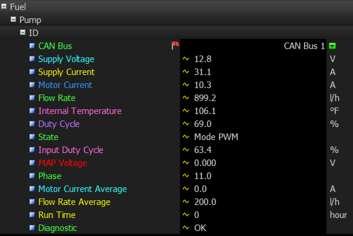
Figure 12: Typical Software Implementation.
When the pump is running the CAN message Status will correspond to the active operation mode.
| Status | Operation Mode |
|---|---|
| 1 | PWM |
| 2 | MAP |
| 3 | Constant Speed |
When the pump is off and has active errors, the CAN message Status will display the Stand By mode.
| Standby Mode | Errors |
|---|---|
| 0 | No Errors |
| 10 | Input Voltage Low |
| 11 | Input Voltage High |
| 12 | Input Current High |
| 20 | Rail Voltage Range |
| 21 | Temperature High |
| 30 | Commutation Lost |
| 31 | No Tacho |
| 32 | Tacho Unstable |
| 33 | No Load |
| 34 | No Start |
| 35 | Output Current High |
| 50 | General Error |
LEDs
There are five LEDs on the control panel of the BPC, four red LEDs to display errors and one green LED to indicate standby or operating.

Figure 13: LED’s
- Standby– When the controller has main and IO cable power but no command to operate the pump, the green LED blinks once every eight seconds.
- Running– When the pump is running, the green LED flashes one second on, one second off.
- Errors– The four red LEDs are used to view, store and recall past errors codes. When there is an active error code, the green LED will remain illuminated while the red LEDs will flash two seconds on, two seconds off. During an active error the pump remains off. The active error will be reset when the power is cycled or the controller is commanded off.
Please see Error Codes in the Troubleshooting section for details on viewing and clearing error codes.
Troubleshooting
Error Code Button
The error code button is a red, 2.5mm diameter momentary push button located on the controller display panel that allows viewing and deleting stored error codes using four red LEDs.
Viewing Error Codes– With the controller powered on, when the button is pushed the controller will display the most recent error code for two seconds. Each time the button is pushed the error code is cycled to the next oldest. When all four red LEDs illuminate there are no older stored codes.
Deleting Error Codes– With the controller powered on, press and hold the error code button until all LEDs illuminate, then release the button. The LEDs will illuminate for four seconds then extinguish. Lastly, cycle power to erase all codes.
Error Codes
| Error Code Definition | Lights | CAN Status |
|---|---|---|
No Error
|
|
0 |
Input Voltage Low
|
|
10 |
Input Voltage High
|
|
11 |
Rail Voltage Range
|
|
20 |
Input Current High
|
|
12 |
Controller Temperature High
|
|
21 |
Commutation Lost
|
|
30 |
Tachometer Unstable
|
|
32 |
No Start
|
|
34 |
High Output Current
|
|
35 |
Switch Error
|
|
77 |
General Controller Error
|
|
50 |
Troubleshooting Table
| Observation | Recourse |
|---|---|
| Pump intermittent/erratic during operation | If the pump turns off momentarily or is erratic, the controller may be switching between operation modes.
It is imperative to limit the PWM input duty cycle to 99% or less. If the duty cycle reaches 100%, the controller will engage in a different operation mode. |
| Pump output does not change with changing MAP pressure | If the pump speed changes with the adjustment of the SPEED dial, the controller is not in MAP mode. Alternatively, the operation mode can be verified with the CAN channel “Status” (see CAN output section). |
Specifications
Operating Parameters
- Operating Voltage: 7.0 to 17.5 volts DC (w/ Reverse Polarity Protection)
- Over Voltage Protection (Input): 17.5v (from off state), 18.5v (while on)
- Under Voltage Protection (Input): 7.5v (from off state), 7v (while on)
- Over Current Protection (Input): 120 Amps
- Max Operating Input Current: 100 Amps
- Max Standby Current: 100 mA
- Max Off Current: 20 mA
- Max MAP Sensor Supply Current: 20 mA
- Weight: 5.2 lbs. (2.37 kg)
- Maximum Ambient Temperature: 70°C (output loading dependent)
- Minimum Ambient Temperature: -18°C
Input/output pin descriptions
Low-level inputs and outputs are accomplished through a single 15 pin D-Sub cable.
Suitable IO extension wire: 18-26 AWG
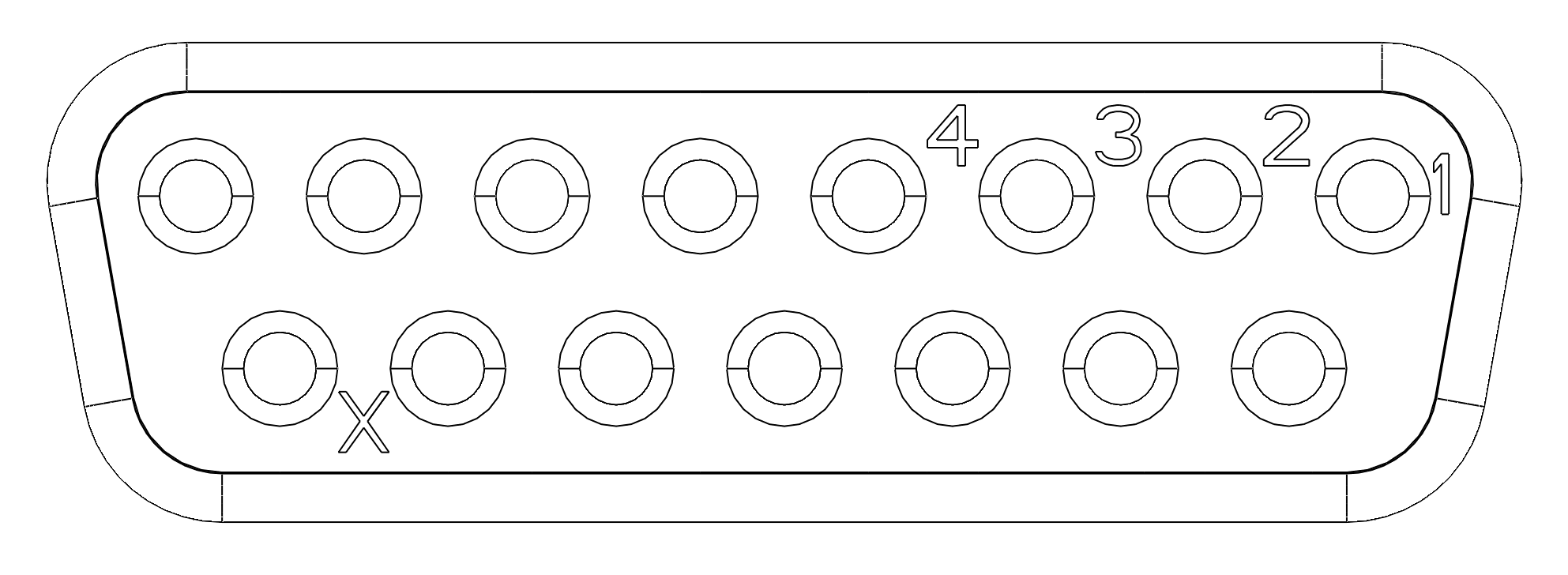
Figure 14: Looking into the controller side of the 15 pin D-sub connector (X indicates pin 15).
| Signal | Wire Color | IO Cable Pin | Description |
|---|---|---|---|
| ON/OFF | Red | 1 | Ignition switched, battery +
hot during cranking, 7 vdc (min) |
| ON/OFF Ground | Black | 9 | Ground for turning on controller |
| PWM + | Red / White | 2 | PWM positive input, 5 vdc (min) |
| PWM – | Black / White | 10 | PWM negative input, ground |
| Flowrate Power | White | 3 | Power supply (input) for Flowrate circuit, 5 vdc (min) |
| Flowrate Ground | Brown | 11 | Ground for Flowrate circuit,
chassis ground |
| Flowrate Signal | Pink | 4 | Digital signal output to logger for flowrate datalogging |
| CAN Hi | Yellow | 5 | CAN IO Hi |
| CAN Lo | Blue | 6 | CAN IO Low |
| MAP Ground | Green | 14 | Ground output to MAP sensor |
| MAP Power | Orange | 15 | 5 vdc output to MAP sensor,
20mA max ONLY USE FOR MAP SENSOR |
| MAP Signal | Purple | 8 | MAP sensor signal input,
0.5 to 4.5 vdc |
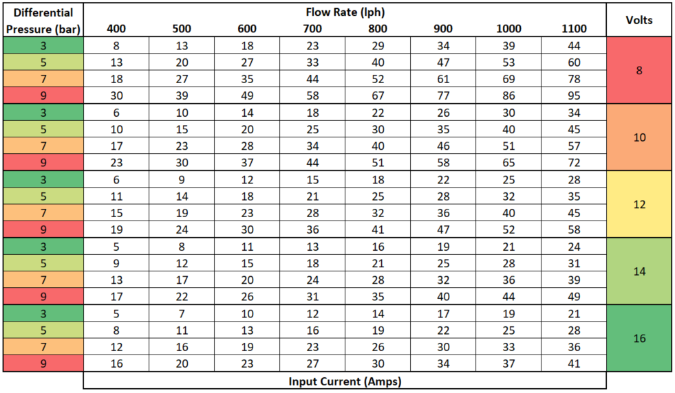
Nominal Current draw
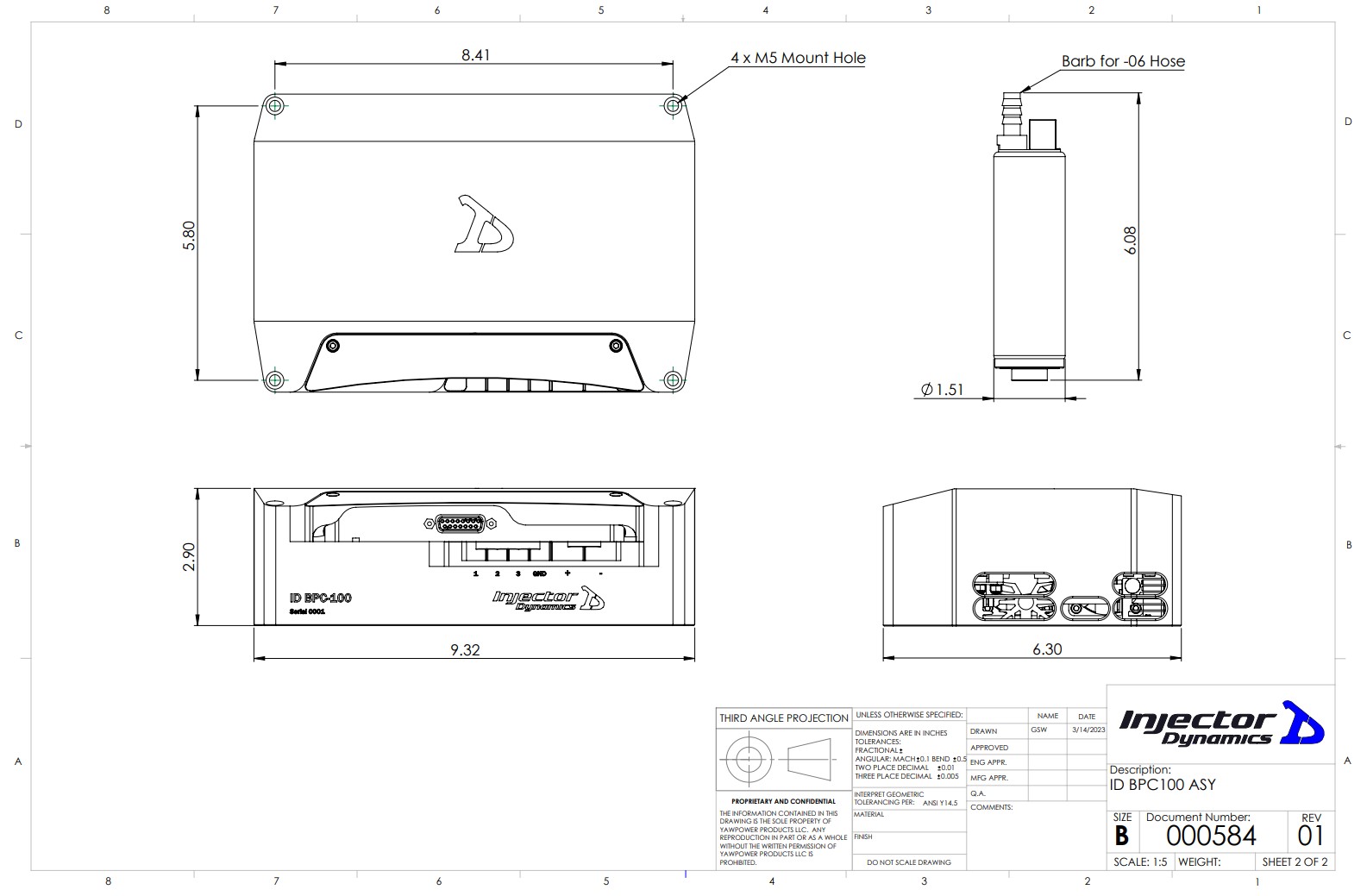
Physical Dimensions
Downloads