
![]()
Contents
Fuel Rail + Regulator Kit (Return Style Kit)
- Remove Fuel Pump Module
- Modify Fuel Pump Module for Return Line and Regulator Plug Install
- Install Fuel Rail, Injectors and Regulator
- Install Fuel Lines
- Flash ECU
- Reinstall All Remaining Parts
Fuel Rail + Pulsation Damper Kit (Returnless Kit)
- Access Fuel Pump Module
- Install Fuel Rail, Injectors and Pulsation Damper
- Install Fuel Lines
- Flash ECU
- Reinstall All Remaining Parts
Application Notes
Supported Models : 2017-2022 Can Am Maverick X3 with the Turbocharged 0.9L I3 engine.
Note: The vehicle shown in this document is a modified 2020 Can Am Maverick X3 Turbo RR. Your vehicle could have parts that may or may not be present in the pictures. The images are meant to be a reference only.
If you have any questions regarding your installation please contact us at support@injectordynamics.com
Item List
| Item No. | Description | Qty. | Fuel Rail + Regulator Kit (Return Style Kit) | Fuel Rail + Pulsation Damper Kit (Returnless Kit) | Fuel Rail Upgrade Kit |
|---|---|---|---|---|---|
| 1 | CAN AM X3 Fuel Rail | 1 | |||
| 2 | CAN AM X3 OEM Fuel Line Fitting* | 1 | |||
| 3 | 3 Bar Regulator Pressure / Pulsation Damper ASY | 1 | |||
| 4 | Stock Fuel Pressure Regulator Plug (Includes O ring) | 2 | |||
| 5 | 90° MAP Reference Fitting | 1 | |||
| 6 | 06 ORB to 06AN Male* | 1 | |||
| 7 | 06 ORB Plug | ||||
| 8 | 06 ORB to 04AN Male | 1 | |||
| 9 | 06 ORB to 06 ORB Coupler | 1 | |||
| 10 | 90° 06AN Male to 3/8″ EFI (Press On) | 1 | |||
| 11 | 06AN E85 Rated Hose (111″) | 1 | |||
| 12 | 06AN Straight Crimp Fitting | 1 | |||
| 13 | 06AN 180° Crimp Fitting | 1 | |||
| 14 | 04AN E85 Rated Hose (100″), 90° and 45° Crimp ends | 1 | |||
| 15 | 04AN Straight Bulkhead | 1 | |||
| 16 | 04AN Bulkhead Nut | 1 | |||
| 17 | 04AN Stat-O-Seal | 1 | |||
| 18 | 7/16″ External Tooth Lock Washer | 1 | |||
| 19 | 4mm to 8mm Barb Reducer | 1 | |||
| 20 | 8mm Black Silicone Hose (5.5″) | 1 | |||
| 21 | 4mm Black Silicone Hose (4″) | 1 | |||
| 22 | 11″ Cable Tie | 5 | |||
| 23 | 3″ Miniature Cable Ties | 4 | |||
| 24 | Injector Clip | 3 |
*Fuel Upgrade Kit will include either the OEM or 06 ORB to 06 AN fitting depending on the vehicle’s feed line.
Fuel Rail + Regulator Kit (Return Style Kit)
1. Removing the Fuel Pump Module
- Remove the right-side dashboard panel shown in figure 1 to gain access to the fuel pump. Remove the metal connector cover
- Disconnect the power connector and crank the engine to bleed fuel pressure. Disconnect battery once the pressure has bled.
- Disconnect the fuel line from the pump module. There may be fuel left in the fuel line.
- Remove the fuel pump locking ring and lift the module out of the tank (drain as much fuel back into the tank as possible).
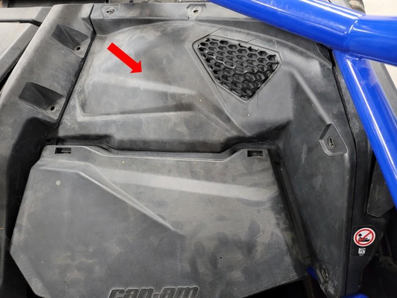
Figure 1: Dashboard panel reference.
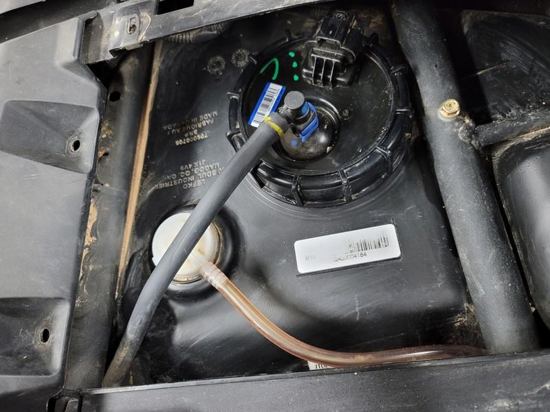
Figure 2: Factory feed line and connector reference
2. Modify Fuel Pump Module for Return Line and Regulator Plug Install
- Drill a 7/16” hole directly on the indent shown in figure 3. We recommend a Unibit, but it is also possible to start with a smaller drill bit and step up to a 7/16” bit.
- Install the -04 straight bulkhead fitting. Use the stat-o-seal on the top of the pump module and the external tooth lock washer on the bottom.
- Install the EFI adapter onto the outlet of the fuel pump module. Pull on the adapter to ensure proper installation.
- Determine which version fuel pump you have using figure 4 and 6. Follow the corresponding steps to install the regulator plug.
- For the pump shown below, remove the stock fuel pressure regulator by lifting the cover straight up and rotating 90°. Use figure 4 as reference.
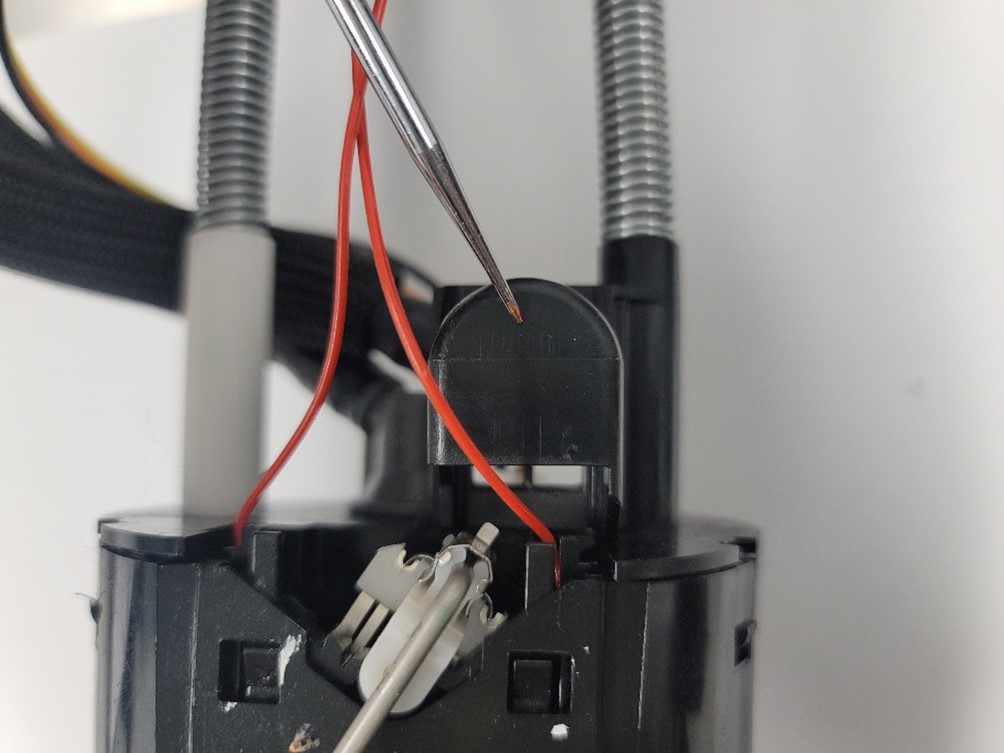
Figure 4: Fuel Pressure Regulator Cover.
- Remove the fuel pressure regulator from the housing.
- Press the larger regulator plug into the housing. Use figure 5 as reference.
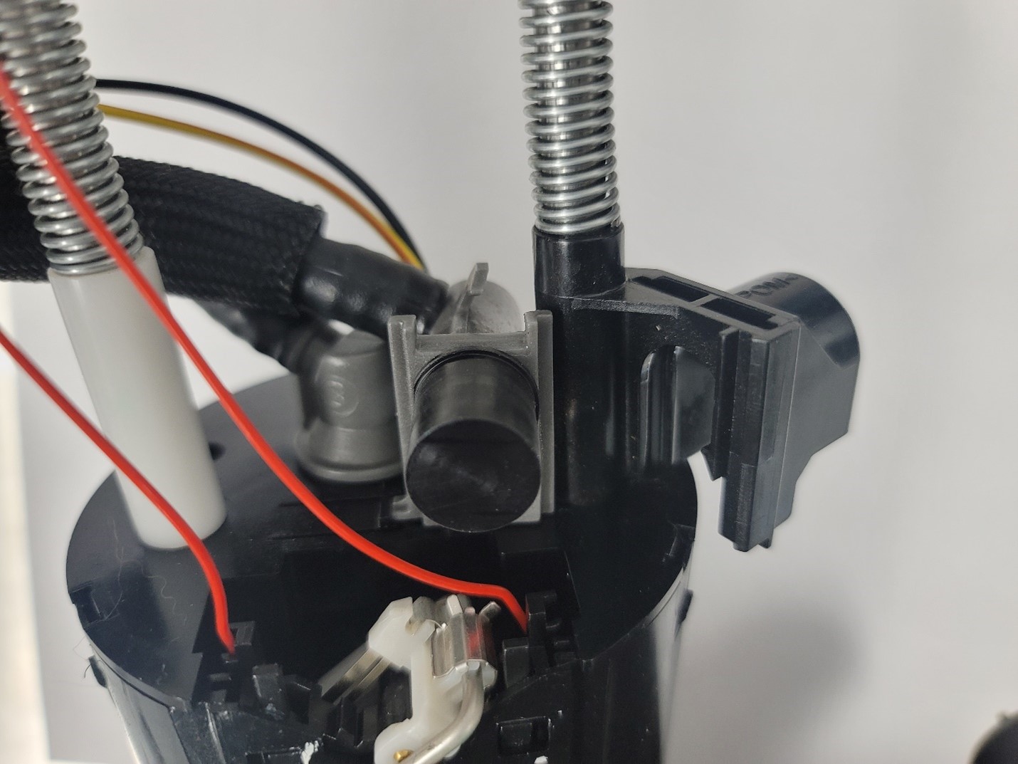
Figure 5: Regulator Plug Reference
- Slide cover back over the regulator plug.
- For the pump shown below, remove the stock fuel pressure regulator by lifting both top and bottom tabs on the gray plastic cover and remove the cover. Use figure 6 as reference.
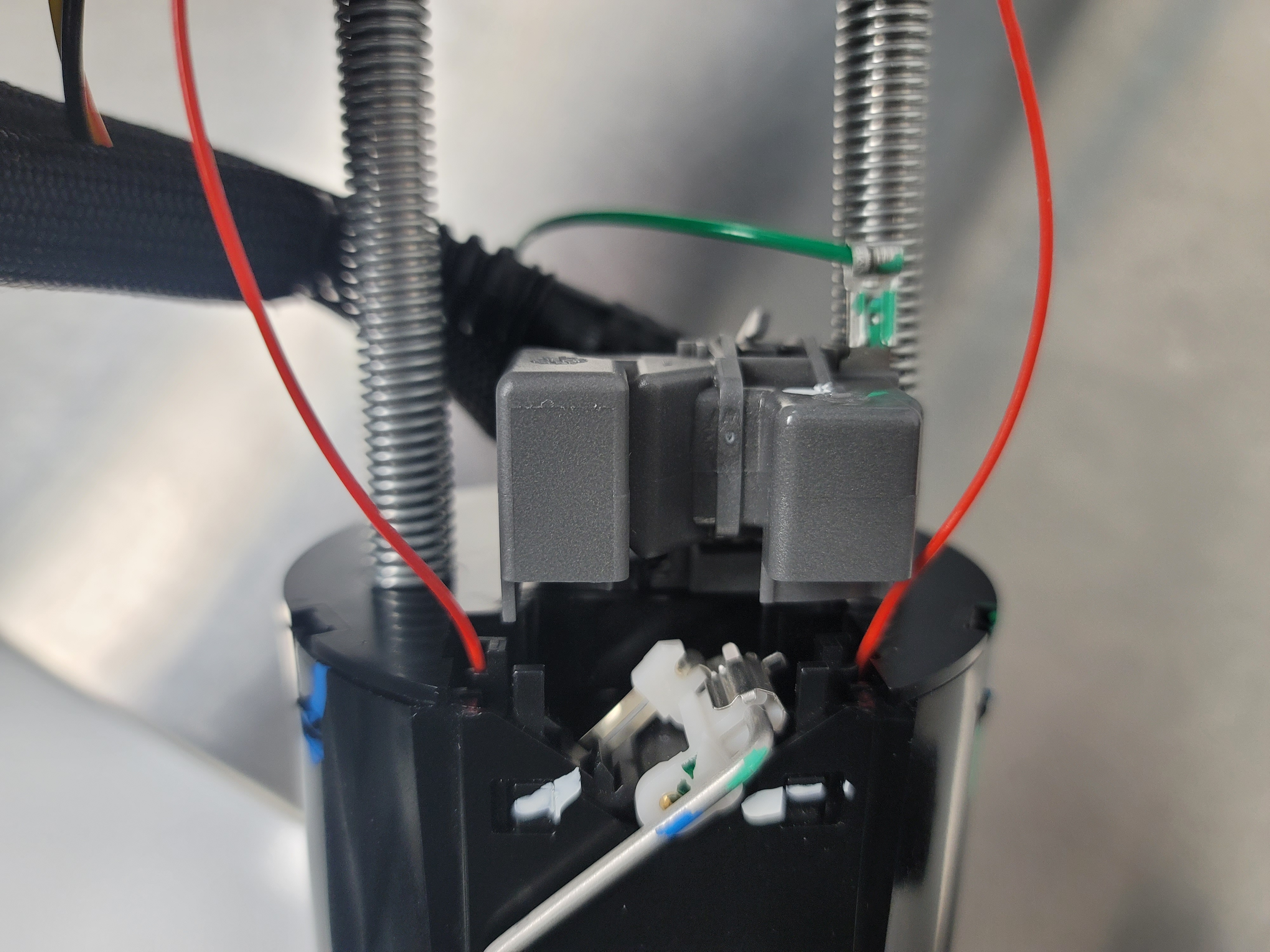
Figure 6: Fuel Pressure Regulator Cover.
- Remove the fuel pressure regulator from the housing and cut the green wire close to the connector. Take care to ensure that the black wire is not cut. Use figure 7 as reference.
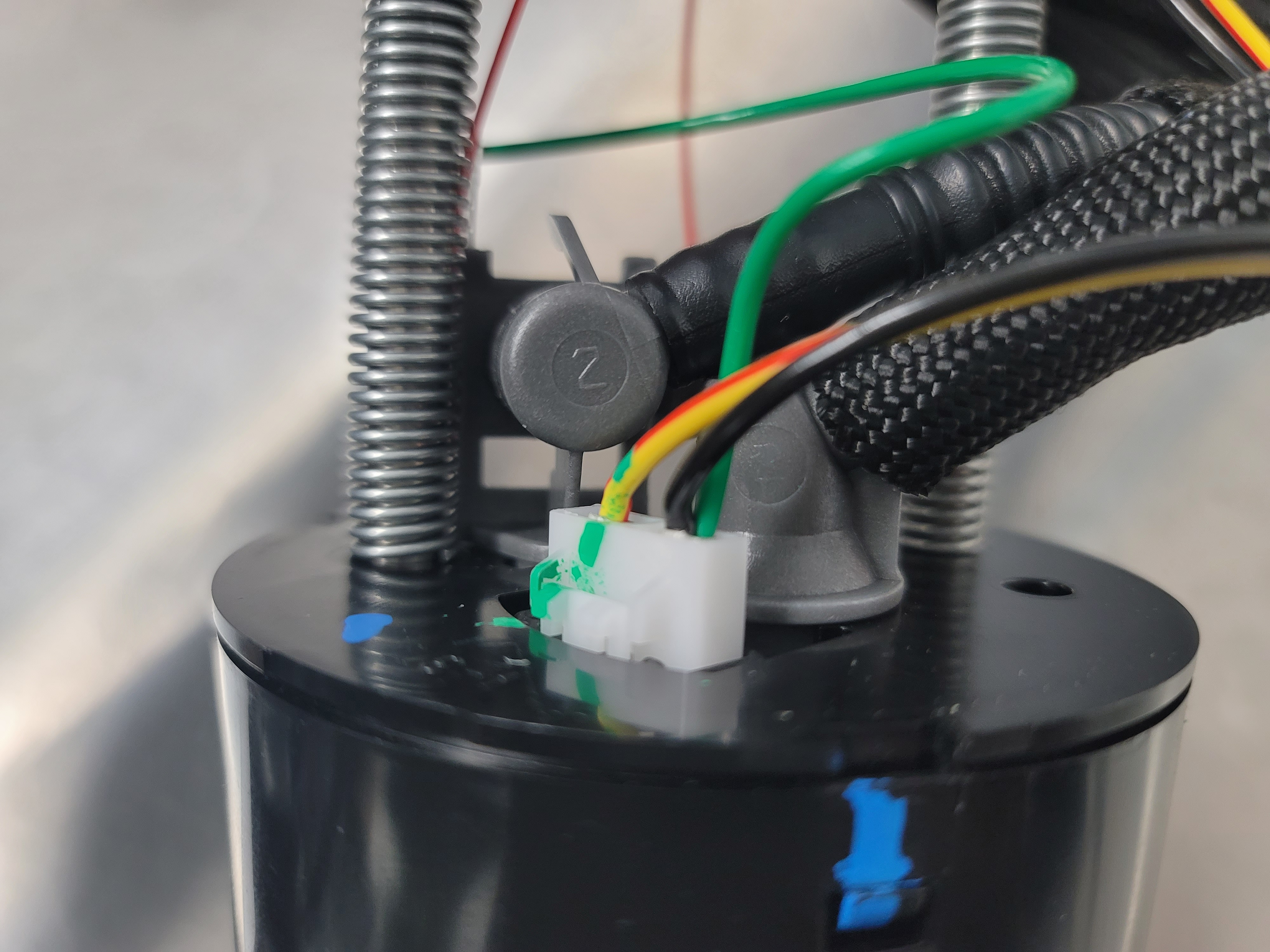
Figure 7: Regulator Wire Reference
- Press the smaller regulator plug into the housing. Use figure 8 as reference.
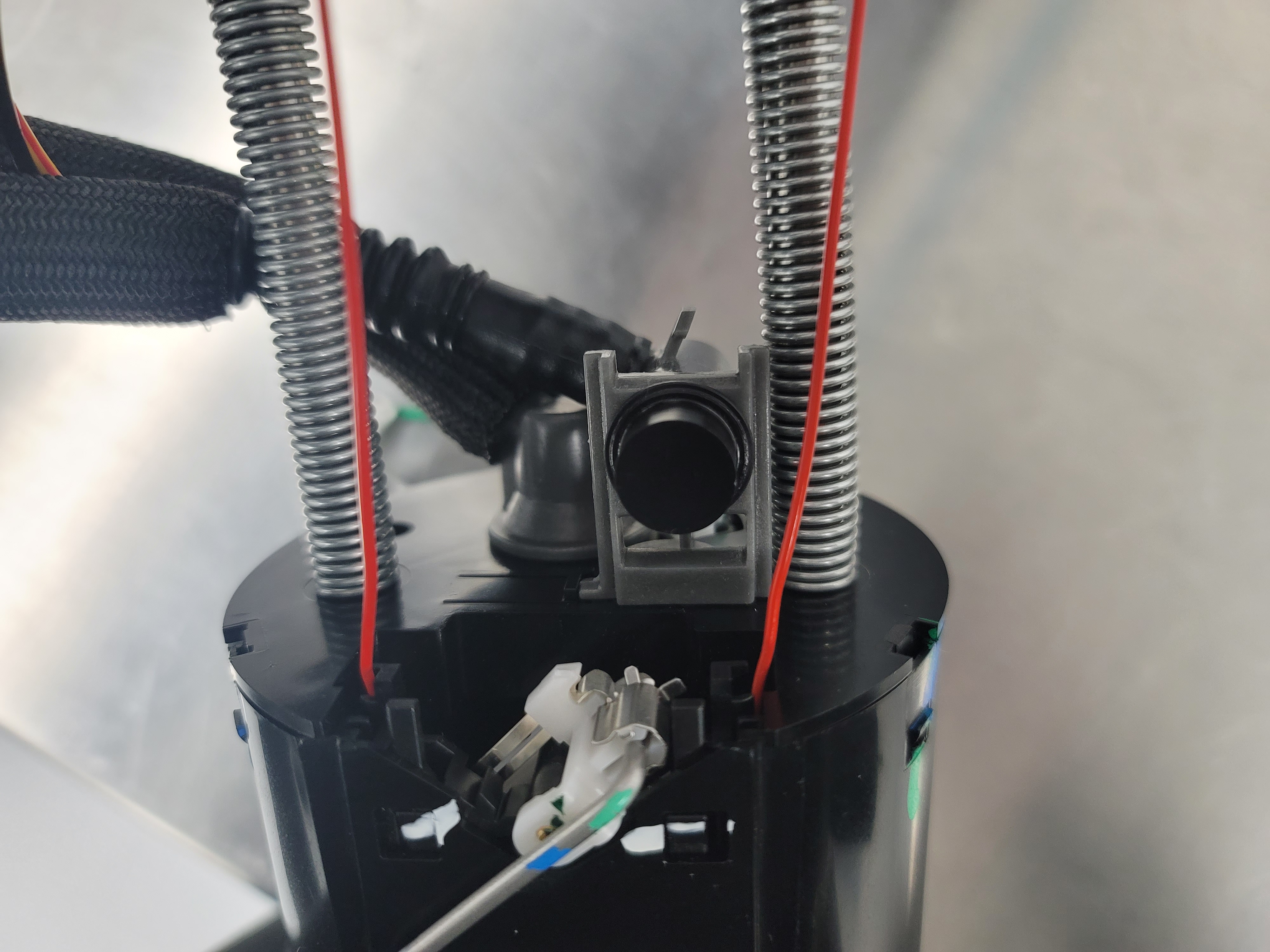
Figure 8: Regulator Plug Reference
- Place the cover back over the regulator plug making sure both tabs lock into place.
- Reinstall fuel pump module into the fuel tank. Use figure 9 as a reference for all connections.
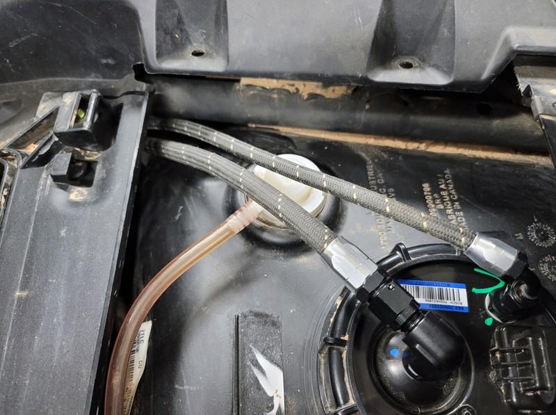
Figure 9: Connection reference
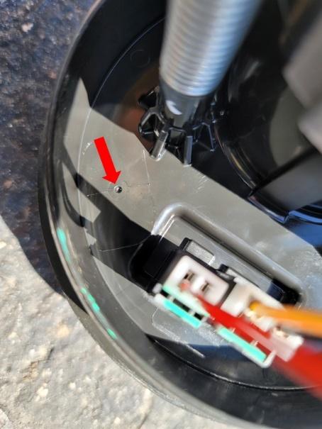
Figure 3: Return Line Hole Reference.
3. Install Fuel Rail, Injectors and Regulator
- Remove rear engine cover.
- Disconnect injector electrical connectors.
- Disconnect fuel line from the rail. There will still be fuel left in the fuel line.
- Remove (2) bolts to uninstall the fuel rail.
- Install the supplied fittings onto the ID rail and regulator.
- Install the -06 ORB to -06 AN on the inlet of the rail (driver’s side).
- Install the non-adjustable side of the -06 ORB swivel fitting on the outlet of the rail (passenger’s side).
- Install the -06 ORB to -04 AN fitting into the bottom of the regulator housing.
- Thread on the regulator housing to the swivel fitting until the threads bottom out, then back out one turn. Do not tighten the lock nut.
- Install the ID injectors on the fuel rail using the supplied retaining clips (Apply grease on all O-rings).
- Install the fuel rail and injectors onto the manifold. Ensure all injectors are firmly seated (Do not over tighten bolts).
- Orientate the fuel pressure regulator with the outlet pointing straight down and tighten the lock nut to the regulator housing.
- Attach injector connectors using supplied electrical adapters.
- Install the 90° MAP reference fitting and connect the vacuum hoses:
- Remove the block off plate shown in figure 11.
- Transfer the o-ring to the supplied 90° fitting and install the fitting into the intake manifold. Use figure 12 as reference
- Push on the supplied 8mm vacuum hose onto the 90° fitting.
- Insert the hose barb reducer into the other end of the 8mm hose.
- Push on the supplied 4mm vacuum hose onto the other end of the reducer.
- Trim any excess length of the vacuum hose and push onto the pressure regulator barb.
- Secure zip ties (small) to each connecting end of the vacuum hoses.
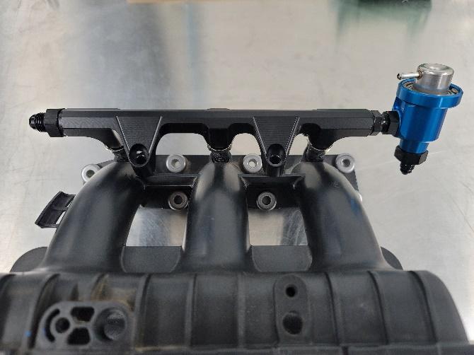
Figure 10: Fuel Rail reference
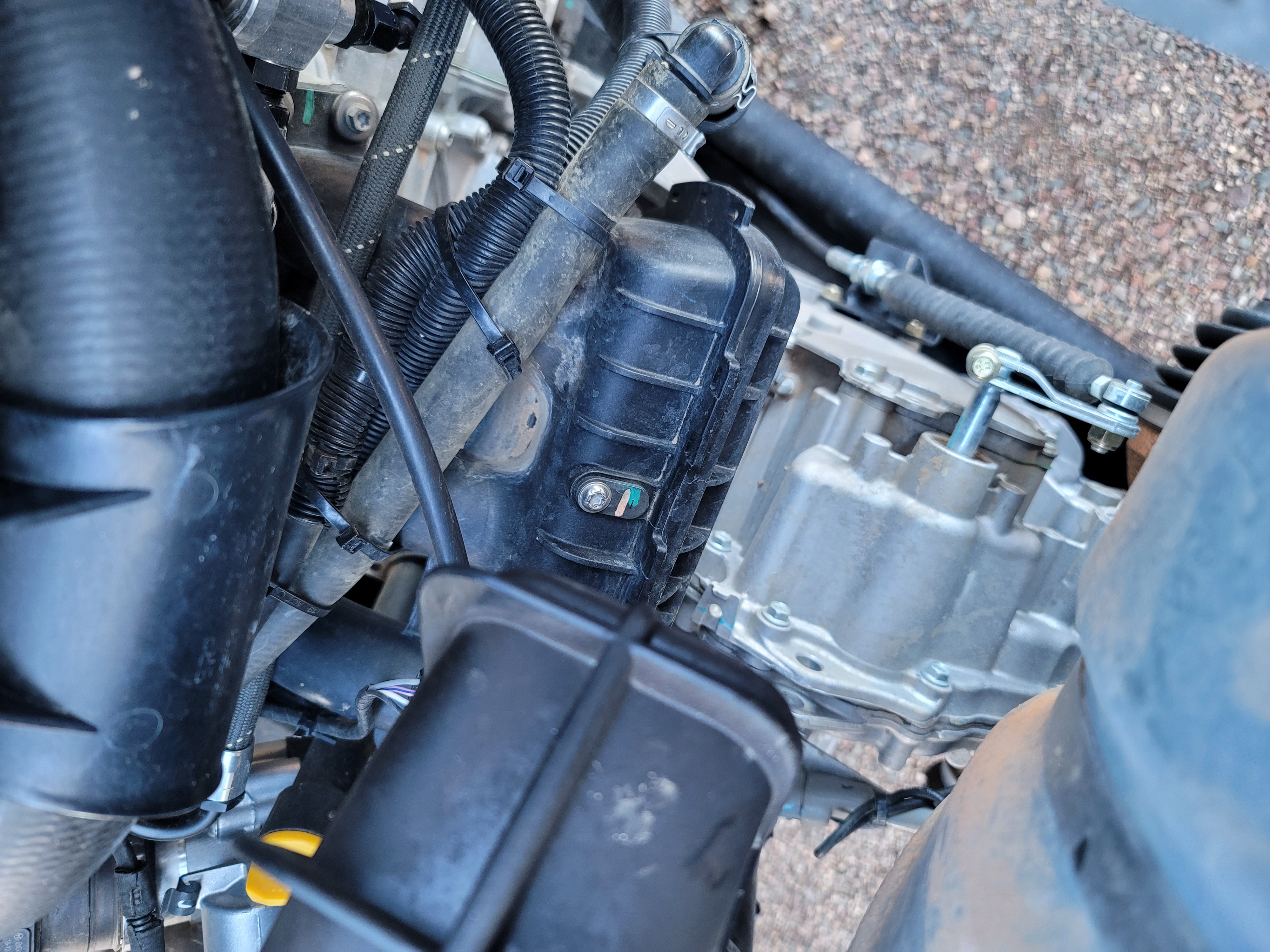
Figure 11: Block Off Plate Reference
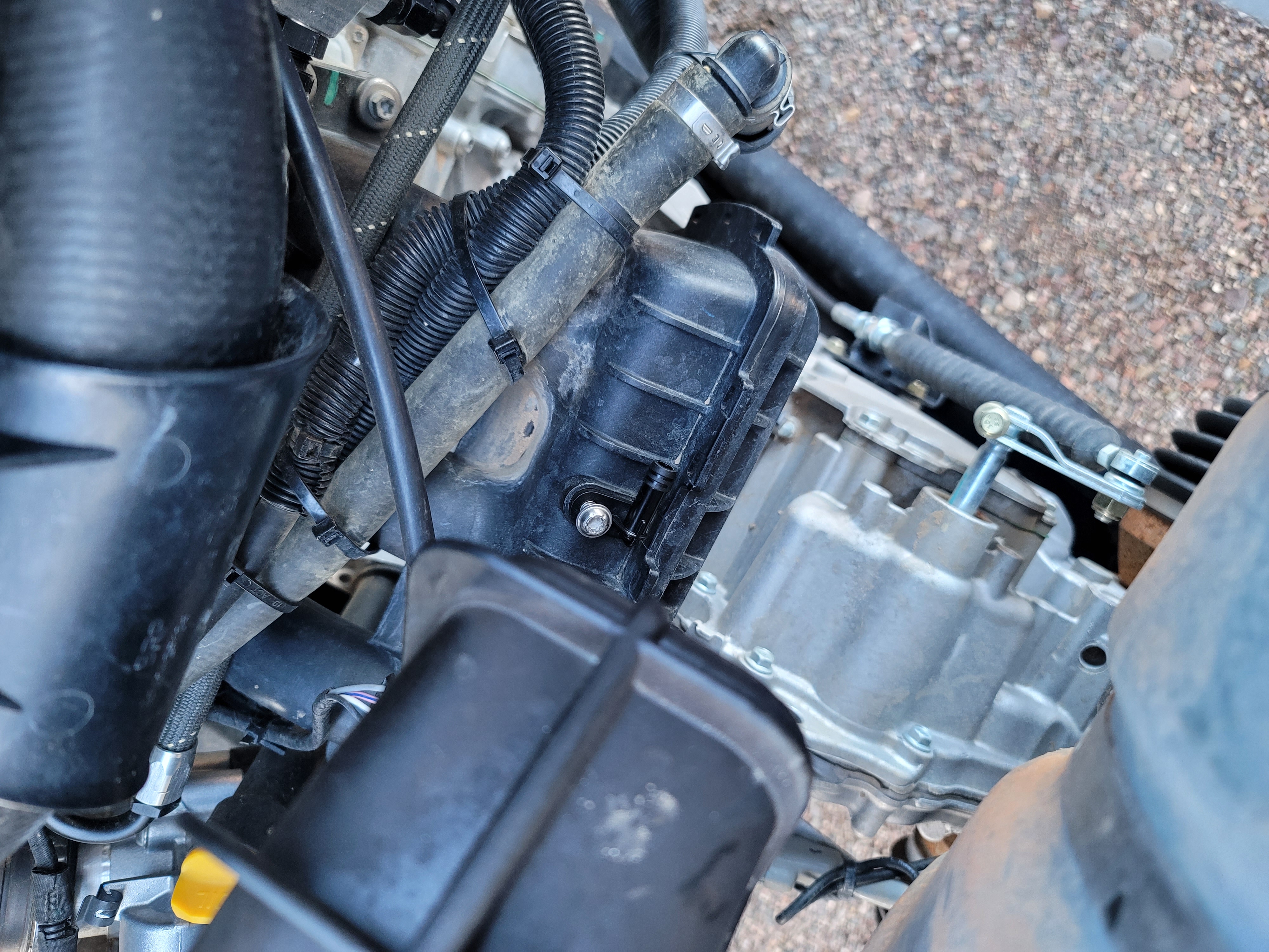
Figure 12: 90° Fitting Reference
4. Install Fuel Lines
- Remove the passenger seat by removing (2) nuts from the front of the seat rail, (2) two nuts to the rear of the seat rail, and the bolts fastening the shoulder belts to the seat.
- Remove the right side lateral dash panel by removing all hardware and pulling the panel out of the retaining clips.
- Remove the lower dash panel shown in figure 13.
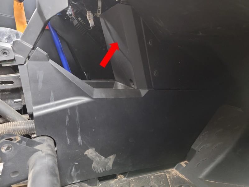
Figure 13: Lower Dash Panel Reference
- Remove the rear hose support clip located at the firewall by pulling the clip towards the front of the car. Make note of the correct orientation for reinstallation.
- Remove the hose support cover (shown in figure 14) by uninstalling all hardware.
- Remove the factory fuel line from the vehicle. To do this, disconnect the two hoses in the center console. (Shown in figure 15).
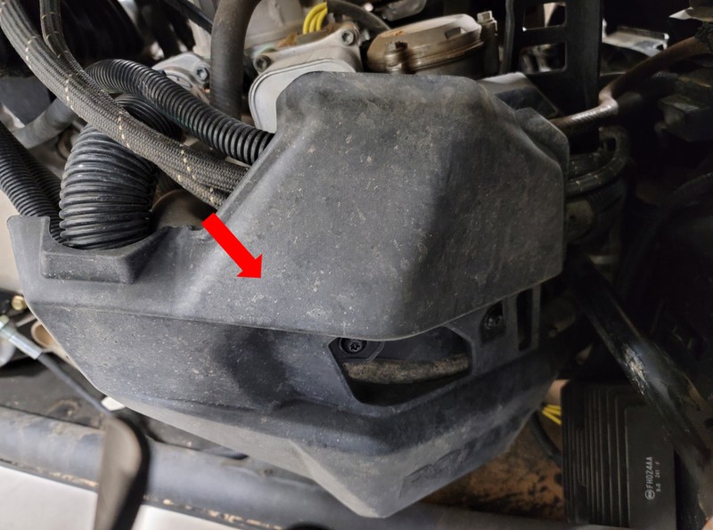
Figure 14: Rear hose support cover.
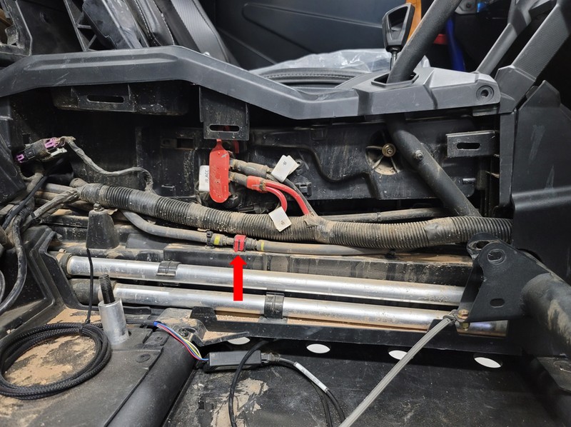
Figure 15: Center Fuel Line Connector
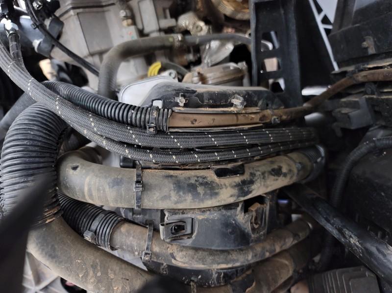
Figure 16: Hose Routing Reference
- Starting with the -06 feed line, connect the 180° fitting to the fuel rail on the driver’s side. Route the new feed hose in the same location as the OEM fuel line.
- Connect the straight connector to the EFI adapter.
- Connect the 45° fitting of the -04 return line to the outlet of the fuel pressure regulator. Route return line along the feed line towards the fuel tank.
- Connect the 90° fitting to the bulkhead fitting.
- Zip-tie fuel hoses together along the center console.
- Reconnect battery and prime the fuel system to check for leaks. Do not start vehicle.
5. Flash ECU
- Generate ECU data by using the online generator at the inks below and follow the directions to change the calibration.
- Once the ECU flash is complete, start the vehicle. Ensure that there are no leaks in the fuel system (Caution: It is best to have a fire extinguisher within reach).
Dynojet PV3 Can Am Data Generator
HP Tuners Can Am Data Generator
6. Reinstall All Remaining Parts
- Once you have ensured there are no leaks, reinstall all body panels and seats in the reverse order of removal.
Fuel Rail + Pulsation Damper Kit (Returnless Kit)
1. Access Fuel Pump Module
- Remove the right-side dashboard panel (ref figure 1) by unfastening all hardware to gain access to the fuel pump. Remove the metal connector cover
- Disconnect the power connector and crank the engine to bleed fuel pressure. Disconnect battery once the pressure has bled.
- Disconnect fuel line from the pump module. There may be fuel left in the fuel line.
- Install the EFI adapter onto the outlet of the fuel pump module. Pull on the adapter to ensure proper installation.
Figure 1: Dashboard pane/ reference.
Figure 2: Factory feed line and connector reference
2. Install Fuel Rail, Injectors and Pulsation Damper
- Remove rear engine cover.
- Disconnect injector electrical connectors.
- Disconnect the fuel line from rail. There will still be fuel left in the fuel line.
- Remove (2) bolts to uninstall the fuel rail.
- Install the supplied fittings onto the ID rail and damper housing.
- Install the -06 ORB to -06 AN on the inlet of the rail (driver’s side).
- Install the non-adjustable side of the -06 ORB swivel fitting on the outlet of the rail (passenger’s side).
- Install the -06 ORB plug into the bottom of the damper housing.
- Thread on the damper housing to the swivel fitting until the threads bottom out, then back out one turn. Do not tighten the lock nut.
- Install ID injectors on the fuel rail using supplied retaining clips (Apply grease on all O-rings).
- Install fuel rail and injectors onto the manifold. Ensure all injectors are firmly seated (Take care, not to over tighten bolts).
Figure 3: Fuel Rail Reference
- Orientate the fuel pulsation damper with the outlet pointing straight down and tighten the lock nut to the damper housing.
- Attach the injector connectors using the supplied electrical adapters
3. Install Fuel Lines
- Remove the passenger seat by removing (2) nuts from the front of the seat rail, (2) nuts to the rear of the seat rail, and the bolts fastening the shoulder belts to the seat.
- Remove the right side lateral dash panel by removing all hardware and pulling the panel out of the retaining clips.
- Remove the lower dash panel shown in figure 4.
Figure 4: Lower Dash Panel Reference
- Remove the rear hose support clip located at the firewall by pulling the clip towards the front of the car. Make note of the correct orientation for reinstallation.
- Remove the hose support cover (shown in figure 5) by uninstalling all hardware.
- Remove the factory fuel line from the vehicle. To do this, disconnect (2) hoses in the center console. (Shown in figure 6).
Figure 5: Rear hose support cover.
Figure 6: Center Fuel Line Connector
Figure 7: Hose Routing Reference
- Connect the 180° fitting of the feed hose to the fuel rail (driver’s side). Route new hose in the same location as the OEM fuel line.
- Connect the straight connector to the EFI adapter.
- Secure new feed hose using supplied cable ties.
- Reconnect battery and prime the fuel system to check for leaks. Do not start vehicle.
4. Flash ECU
- Generate ECU data by using the online generator at the inks below and follow the directions to change the calibration.
- Once the ECU flash is complete, start the vehicle. Ensure there are no leaks in the fuel system (Caution: It is best to have a fire extinguisher within reach).
Dynojet PV3 Can Am Data Generator
HP Tuners Can Am Data Generator
5. Reinstall All Remaining Parts
- Once you have ensured there are no leaks, reinstall all body panels and seats in the reverse order of removal.
Fuel Rail Upgrade Kit (-06 Fuel Hose)
1. Access Fuel Pump Module
- Remove the right-side dashboard panel shown in figure 1 by removing all the hardware to gain access to the fuel pump. Remove the metal connector cover
- Disconnect the power connector and crank the engine to bleed fuel pressure. Disconnect the battery once the pressure has bled.
- Disconnect the fuel line from the pump module. There may be fuel left in the fuel line.
- Install the EFI adapter onto the outlet of the fuel pump module. Pull on the adapter to ensure proper installation.
Figure 1 : Dashboard pane/ reference.
Figure 2 : Factory feed line and connector reference
2. Install Fuel Rail and Injectors
- Remove rear engine cover.
- Disconnect injector electrical connectors.
- Disconnect fuel line from the rail. There will still be fuel left in the fuel line.
- Remove (2) bolts to uninstall the fuel rail.
- Install the supplied fittings onto the ID rail.
- Install the -06 ORB to -06 AN fitting on the inlet of the rail (driver’s side).
- Install the -06 ORB plug into the outlet of the rail on the (passenger’s side).
- Install OEM injectors on the fuel rail using the supplied retaining clips (Apply grease on all O-rings).
- Install fuel rail and injectors onto the manifold. Ensure all injectors are firmly seated (Take care, not to over tighten bolts).
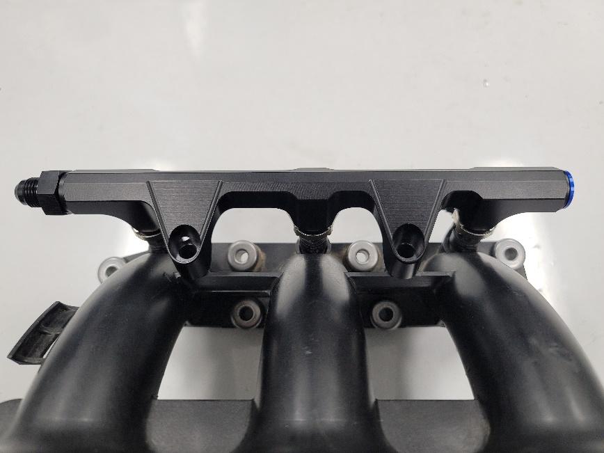
Figure 3 : Fuel Rail Reference
- Attach injector connectors using the supplied electrical adapters.
3. Install Fuel Lines
- Remove the passenger seat by removing (2) nuts from the front of the seat rail, (2) nuts to the rear of the seat rail, and the bolts fastening the shoulder belts to the seat.
- Remove the right side lateral dash panel by removing all hardware and pulling the panel out of the retaining clips.
- Remove the lower dash panel shown in figure 4.
Figure 4: Lower Dash Panel Reference
- Remove the rear hose support clip located at the firewall by pulling it towards the front of the car. Make note of the correct orientation for reinstallation.
- Remove the hose support cover (shown in figure 5) by uninstalling all hardware.
- Remove the factory fuel line from the vehicle. To do this, disconnect the two hoses in the center console. (Shown in figure 6).
Figure 5: Rear hose support cover.
Figure 6: Center Fuel Line Connector
- Connect the 180° fitting of the feed hose to the fuel rail (driver’s side). Route the new hose in the same location as the OEM fuel line.
- Connect the straight connector to the EFI adapter.
- Secure feed hose using the supplied cable ties.
- Reconnect battery and prime the fuel system to check for leaks. Do not start the vehicle.
Figure 7: Hose Routing Reference
4. Reinstall All Remaining Parts
- Once you have ensured there are no leaks, reinstall all body panels and seats in the reverse order of removal.
Fuel Rail Upgrade Kit (OEM Feed Hose)
1. Fuel Rail and Injector Install
- Remove rear engine cover.
- Disconnect injector electrical connectors.
- Disconnect the fuel line from rail. There will still be fuel left in the fuel line.
- Remove (2) bolts to uninstall the fuel rail.
- Install the supplied fittings onto the ID rail.
- Install the -06 ORB plug on the outlet of the rail (driver’s side).
- Install the OEM fitting adapter into the inlet of the rail (passenger’s side).
- Install OEM injectors on the fuel rail using the supplied retaining clips (Apply grease on all O-rings).
- Install fuel rail and injectors onto the manifold. Ensure all injectors are firmly seated (Take care, not to over tighten bolts).
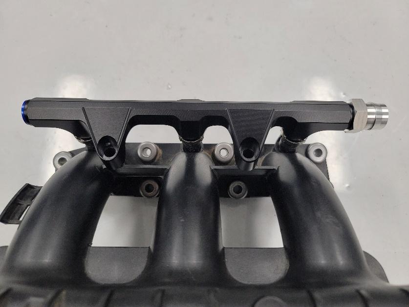
Figure 1: Fuel Rail Reference
- Attach injector connectors using the supplied electrical adapters.
- Reconnect the factory fuel line and prime the fuel system to check for leaks. Do not start the vehicle.
2. Reinstall All Remaining Parts
- Once you have ensured there are no leaks, reinstall all body panels and seats in the reverse order of removal.