Joseph Goebbels, the Minister of Propaganda in Nazi Germany once said “If you tell a lie big enough and keep repeating it, people will eventually come to believe it.”
I cannot say how relevant that statement was in 1940, but in this internet age, it couldn’t be more accurate.
As it relates to fuel injectors, there is a concept that has been coming up a lot lately, often used an excuse for inexpensive injectors that have not been characterized. It seems the more it goes around the more people believe it.
It goes something like this:
Drilling the atomizer plate to increase the flow rate of an injector does not change its offset. The internals have not changed, so the injector response time is the same.
As an extension of that thought, it is assumed that the low pulse adders used in GM software, and the low slope and breakpoint used in Ford software are unchanged as well.
This topic came up on the Corvette forum recently, and I let it twist my little engineer brain into a quivering knot, ready to explode. Then a more sensible man than me suggested that a drilled, and undrilled injector be “put through the tests that ID uses to get their data”
Why didn’t I think of that? It would have saved me a few gray hairs.
The donor injector for this test is a current production EV-14 style injector from Bosch. The raw flow vs pulsewidth curve was generated in the standard manner, the four hole atomizer plate was drilled to increase the flow to near maximum, and then a new flow vs pulsewidth curve was generated.
The raw data is shown below.
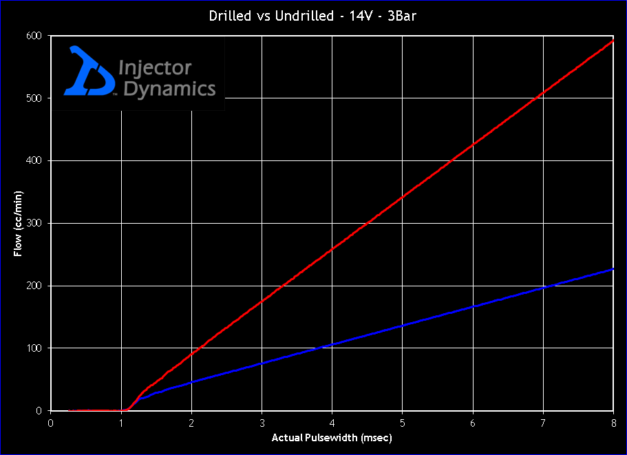
In developing a characterization from raw data, the first step is to define the slope and offset which will describe the output across the majority of the operating range.
This is displayed in the graph below with the defined slope and offset lines overlaid in white.
(Note: The GM characterization tables are described in more detail in this article.)
Unmolested, the injector has a slope (Flow rate) of 301.8 cc/min and an offset of .490 milliseconds. After drilling, the flow rate jumped to 834.9 cc/min with an offset of .905 milliseconds.
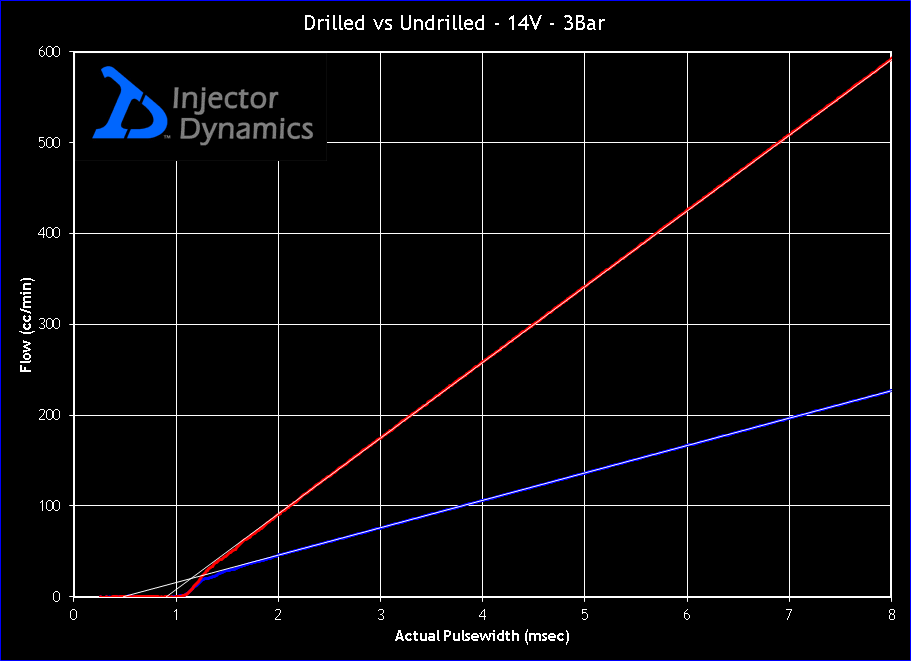
Not “The Same” by any stretch of the imagination, and an offset error that large will result in substantial fueling errors.
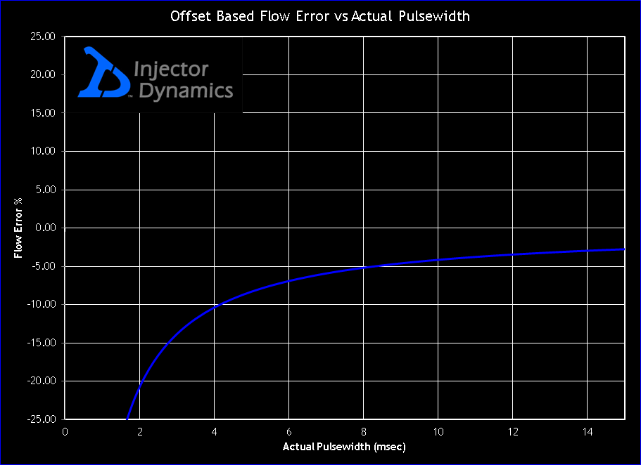
If this injector were used with the new flow rate entered into the IFR table, but with the original offset value, the fuel delivered to the cylinder would be less than commanded. Most notable is that the error would increase as the pulse width decreased.
As the math geeks among you have already guessed, this occurs because the offset error of .415msec is a much bigger percentage of a 2 msec pulse width, than of a 10 msec pulse width.
The chart below shows the error across the pulse width range.
At this point in the article the most obvious question is“If it is that simple to dispel this myth, how did it ever get started, and why has it stuck around?”
I can only guess, but it is clear that most believe, incorrectly, that the injector offset (Also called lag, dead time, latency, battery compensation) is the amount of time the injector takes to open. This opening time is easily measured with an oscilloscope.
Since measuring opening time is easy, but generating an accurate flow vs pulse width curve, performing the appropriate calculations, and doing the homework required to understand it is exceedingly difficult, many have fallen prey to the easy but wrong answer.
Ignoring the fact that the correct information has existed since the mid-seventies, the lie has been repeated enough times that people believed it.
Now that we have the offset issue out of the way, let’s consider the low pulse adders and how they have changed as the result of our modifications.
To help illustrate the point more clearly, the graph below is zoomed in on the low pulse width range of the injector.
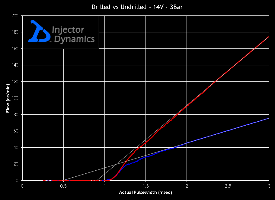
As defined simply by a slope and offset, the output of a fuel injector would follow the lines shown on the graph in white. Put more simply, the white lines represent what the PCM would expect the injector flow to be if we only defined a flow rate and an offset.
As you can see, the actual flow of the injector deviates from these lines dramatically at low pulse widths.
This portion of the flow vs pulse width curve is known as the lower non-linear operating range of the injector, and if we do not account for these non-linearities, our fueling will be incorrect. Specifically, the mixture will be leaner than commanded.
To account for these non-linearities, GM has developed the low pulse width adder table which essentially describes the difference between the actual flow of the injector, and the theoretical flow as defined by the slope and the offset. By adding to the calculated pulse width while operating in this range, the fueling is corrected.
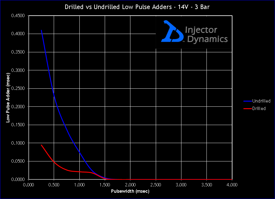
So how much do the low pulse adders change as a result of our modifications?
The graph below shows the required low pulse adders for both versions of the injector. Rather dramatic wouldn’t you say?
If that doesn’t get your attention, consider this… Installing high flow injectors guarantees that you will be operating in the lower non linear range where these tables take effect.
To sum up all of this, modifying the flow of an injector has far reaching effects. The operating characteristics of the injector change entirely, and these errors can take a tuner anywhere from scratching his head, to raping nearly every other table in the ECU to get some semblance of good running vehicle.
At the end of the day, there is no reference point left, and tuning goes from a logical data driven process, to a “poke it with a stick” method that one would expect from the back of a muffler shop.
I hope you found this information helpful.
Thank you for reading.
Paul Yaw
Addendum: 4-14-2011
A sharp man named Mick Hoey (Also known as 5.7ute) requested that I show the effect on Ford characterization. The same raw data is shown in the graph below with Ford’s two slope approximation laid over the top of the raw flow vs pulse width curves.
The values are as follows:

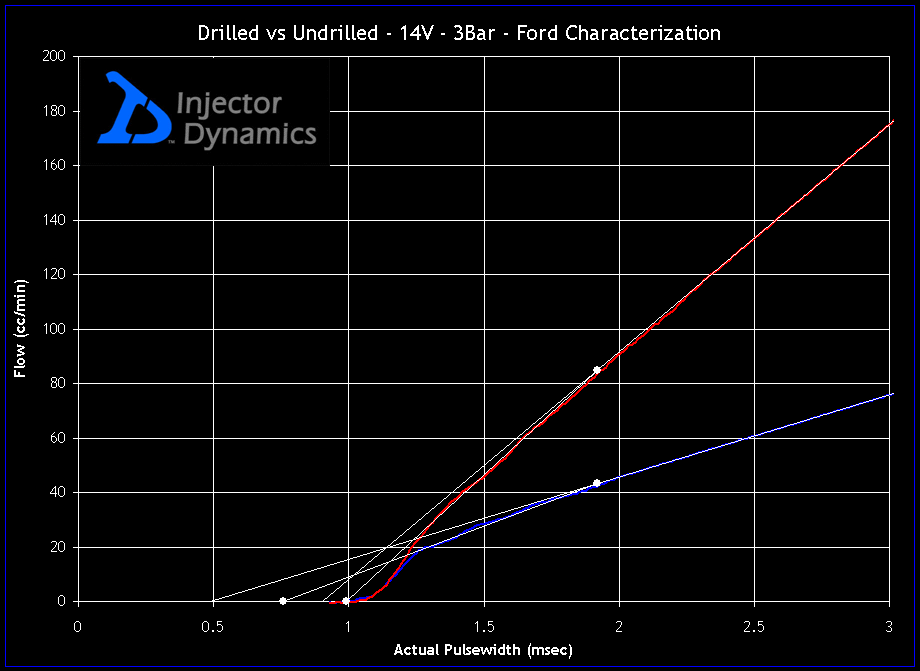
If you’re left scratching your head and wondering what all the lines and dots are about, see this short article for a descrption of Ford injector characterization.
Thanks for the suggestion Mick.
Paul Yaw
Injector Dynamics
