While the injector characterization data used by General Motors is surrounded by mystery and misinformation, its purpose and practical use is actually quite simple.
It is important to understand that the fueling calculations used by GM are based on an air mass per cycle which is then converted to a fuel mass based on the requested air fuel ratio. This is true whether the system is using directly measured airflow from the mass meter, or calculated air flow based on engine displacement, atmospheric conditions, and volumetric efficiency.
Once this fuel mass is determined, calculating the pulse width required to deliver this exact amount of fuel is quite simple…if the dynamic characteristics of the fuel injector are known.
And as we at Injector Dynamics have been preaching from day one, it is the dynamic injector characteristics that matter.
The various tables (offset, flow rate, and low pulse adders) provide a mathematical model of the fuel injectors dynamic response. The PCM uses this data to calculate the injector pulse width that will deliver the requested fuel mass.
At this point it is important to note that this data, if it is to be accurate, comes from dynamic characterization of the fuel injectors in a controlled environment, with equipment capable of measuring the injectors nuances and non-linearities.
Accurate data does not come from an assemblage of tweaked factory values that made your car, or your favorite internet forum “tooners” car run best.
Let’s start by calculating a pulse width value for a known engine and operating condition, based on an injector with a static flow rate of 10.2333 grams per second.
A single cylinder of an LS3 engine running at 85% VE, at standard temperature and pressure will displace .80225 grams of air per induction cycle.
To hit a target air fuel ratio of 13:1, we need a corresponding fuel mass of .06171 grams of fuel.
Knowing that our fuel injector has a static flow rate of 10.2333 grams per second, we divide that into our fuel mass and arrive at a pulse width value of .0060304 seconds, or 6.0304 milliseconds.
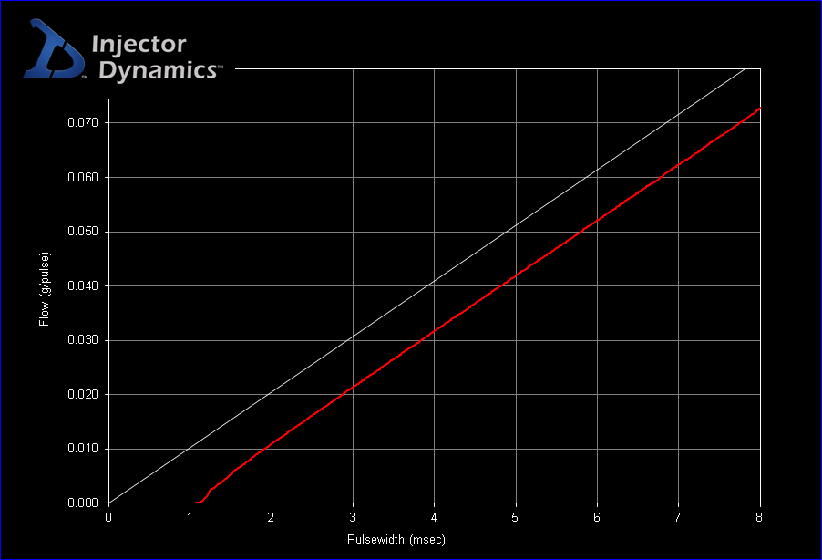
Looking at the red trace below, which is the raw flow vs pulse width data from our injector, we can see that substantial error exists.

The actual fuel delivered by a 6.0303msec pulse width is .05252 grams, which is only 85% of the fuel that we requested!
This flow error is caused by the offset that exists between the actual flow from the injector and the the theoretical flow based on our static flow rate shown in white.
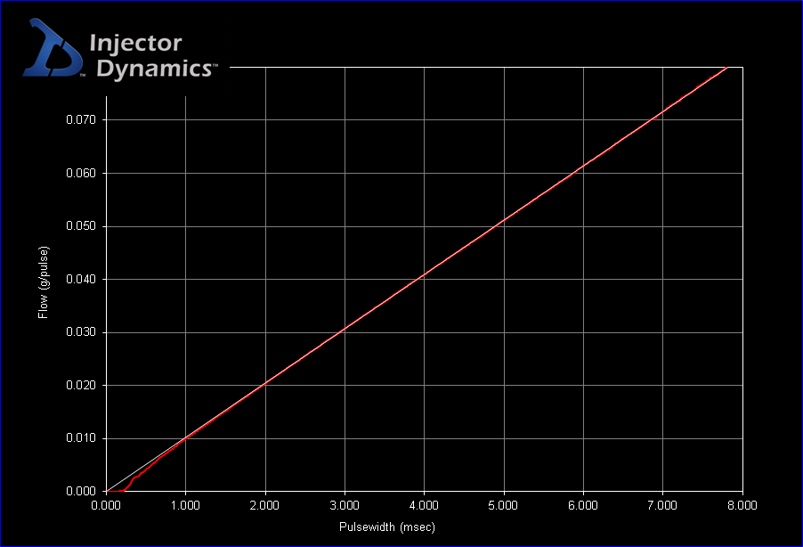
This offset exists with all injectors and needs to be accounted for if want our fuel calculations to be accurate. Because this offset is constant across the majority of the injector operating range, we can correct for it by adding it to our calculated pulse width value.
When we do that, we get the following flow vs theoretical pulse width plot.

We have now corrected the flow across most of the operating range, and can expect our calculated pulse width to deliver the requested fuel mass as long as our injector flow rate, and offset is known.
What complicates the issue is that the flow rate varies with differential pressure, and the offset varies with voltage and differential pressure. These values need to be defined across the entire range of operating conditions if our fueling calculations are to be correct at all times.
This is done by testing the injectors across the appropriate range of voltages and pressures, and populating the 2 dimensional flow tables, and 3 dimensional offset tables in the PCM software.
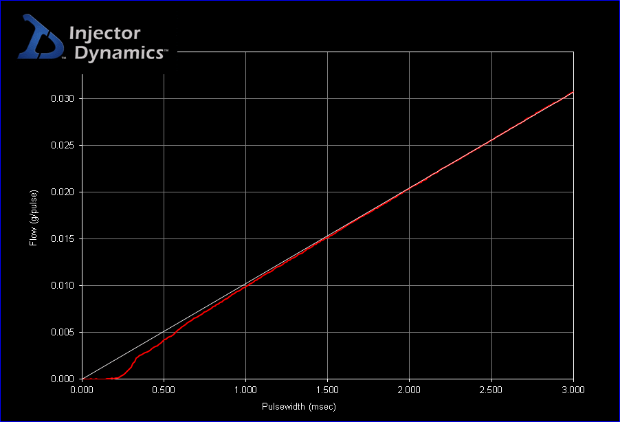
While we can see that our calculations should result in accurate fuel flow rates through the majority of the flow range, we clearly have errors in the low pulse width range, known as the “Lower Non Linear Operating Range” The chart below shows the same plot as above, zoomed in for clarity.

Below 2 milliseconds we have a situation similar to our initial conditions where there was an offset between the actual flow, and theoretical flow of the injector. Unlike the offset within the linear operating range of the injector, this is not constant, and cannot be corrected for with a single value.
The solution is the low pulse adder table which offers offset values that vary with pulse width, correcting the lower non-linear operating range of the injector.
With the addition of these values we can achieve nearly perfect fueling down to practically zero flow, and the PCM can do its job of calculating and commanding the correct air fuel ratio under all operating conditions.
This is a good time to stop and reflect on the enormity of data required to do this. Generating an accurate dynamic injector model takes us approximately 40 man hours under carefully controlled conditions, with equipment designed specifically for this purpose.
Do you really think that these values can be determined experimentally by driving the car and tweaking values to reduce your short and long term trims?
Do you even want to try?
Knowing that your mass air calibration and VE table values will inevitably be altered as a result of your performance modifications, an accurate fuel model is the last reference point available to you. Without it, you are truly left without a clue.
And while companies like Vortech Engineering have paid us hefty test fees to generate accurate injector data for their emissions legal performance kits, we provide it for free with all Injector Dynamics injectors.
Do you really want to tune with anything else?
Thanks for reading.
Paul Yaw
Injector Dynamics
